Turbocharger
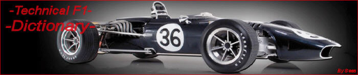
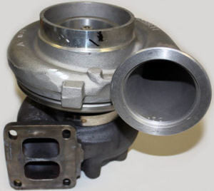
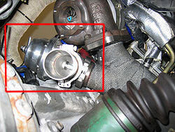
From year 2014 Formula 1 governing body FIA, announced new set of rules, and between them one concerning engine. New engines are 1600ccm V6 turbocharged. Main motivation for this change was obligation of Formula 1 community to go more “green”, use technology which can be transferred to production cars and to save some money. On picture below you can see Renault Formula 1 turbocharger for 2015 V6 engine.
So, let see what is turbocharging and how it works. In this article we will talk only about turbocharger itself, no ERS-H. To know more about new set of rules, new engines, ERS-H and ERS-K, this follow this link.
History
Basic description of this is “wind mill on one side of the shaft, air pump on other side of the shaft”. This concept is old thousands of years, but turbocharger used with engines was invented by Swiss engineer Alfred Büchi. His patent for a turbocharger was applied for use in 1905. Diesel ships and locomotives with turbochargers began appearing in the 1920s. During the First World War French engineer Auguste Rateau fitted turbo chargers to Renault engines powering various French air fighters with some success. In 1918, General Electric engineer Sanford Moss attached a turbo to a V12 Liberty aircraft engine. The engine was tested at Pikes Peak in Colorado at 14,000 feet (4,300 m) to demonstrate that it could eliminate the power losses usually experienced in internal combustion engines as a result of reduced air pressure and oxygen deprivation at high altitude.
Turbochargers were first used in production aircraft engines in the 1930s before World War II. The primary purpose behind most aircraft-based applications was to increase the altitude at which the airplane could fly.
 |
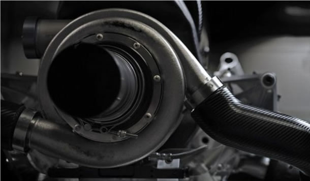
A-body Oldsmobile Cutlass Jetfire and his shifter with turbo pressure gauge |
The first production turbocharged automobile engines came from General Motors in 1962. The A-body Oldsmobile Cutlass Jetfire and Chevrolet Corvair Monza Spyder were both fitted with turbochargers. Saab was the first manufacturer to have successfully applied a turbo to regular production cars. This was made possible by the introduction of a wastegate to relieve excess pressure.
The world's first production turbo diesel automobiles were the Mercedes 300SD and the Peugeot 604, both introduced in 1978. Today, most cars with diesel engines are turbocharged.
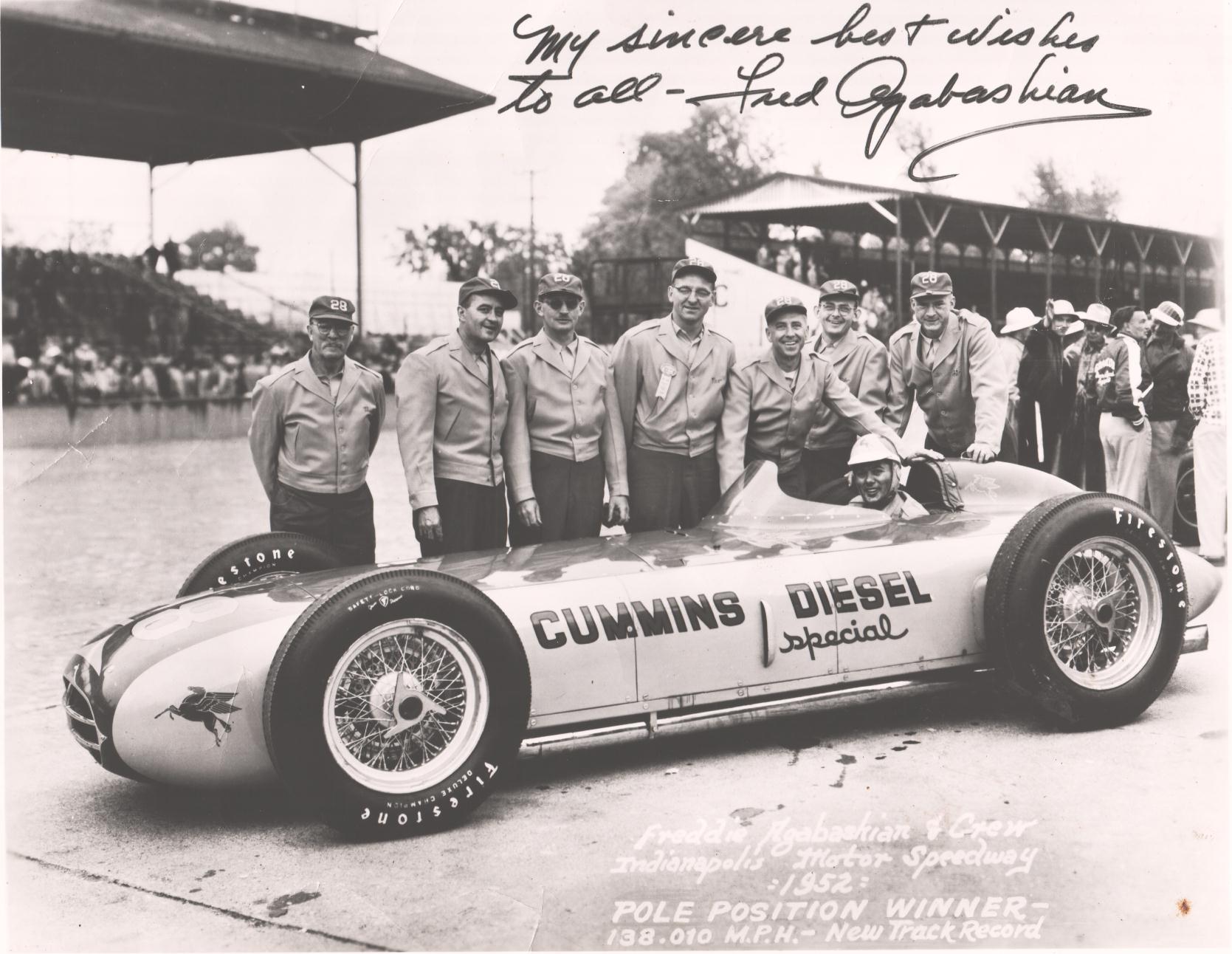 |
Clessie L. Cummins had been experimenting with turbocharging to replace the heavy superchargers. At this time the Indy rules gave blown (supercharged or turbocharged) diesels a maximum displacement of a 6.6 liter (402.7 cubic inches). Clessie and his brother Don were interested in it with a specially built racing engine of 6.597 liter (402.6 cubic inches), lightened with aluminum and magnesium. Output was a serious 380 horsepower. The chassis builder was Frank Kurtis, whose Kurtis Craft had built several winning cars for Indy. Kurtis had been experimenting with placing the driveshaft alongside the driver’s left hip, shifting weight, and lowering the overall height of the car. Mounting the engine horizontally, rather than vertically, added to the sleek design. At its cowl, the car was 58.4 centimeters (23 inches) tall! However, it weighed 3,100 pounds, compared to the 2,000 pound average weight of the other entries. The engine was 750 pounds on its own. On the first day for qualifying, as the first entrant on the track, the big diesel roadster completed its 4 lap qualification at 138.010 miles per hour, a new track record. It stunned all the other 32 competitors, including Team Ferrari, the only foreign entry. Leading the race till lap 70, the diesel began to spit huge clouds of black smoke. A pit stop was made, but two laps later, the car retired. Later, an inspection revealed that the air intake for the Elliot turbo charger had become clogged with bits of rubber from the race track. An ill placed inlet was the failure, not the engine itself. On left, picture of the team with enlarged Fred Agabashian sign and "Thank-you" note. Click on picture to get bigger version. |
The first successful application of turbocharging in car racing appears to have been in 1952 when Fred Agabashian in the diesel-powered Cummins Special (above) qualified for pole position at the Indianapolis 500 and led the race for 175 miles (282 km). Offenhauser's turbocharged engines returned to Indianapolis in 1966, with victories coming in 1968. The Offenhauser turbo peaked at over 1,000 hp (750 kW) in 1973, while Porsche dominated the Can-Am series with a 1,100 hp (820 kW) 917/30. Turbocharged cars dominated the 24 Hours of Le Mans between 1976 and 1988, and then from 2000-2010. Turbo-diesel era in 24 Hours of Le Mans racing begin with Audi R10 LMP prototype car. Since then, diesels are only winners in highest class of this race were turbo-diesels (down).
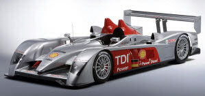 |
On December 13th 2005 Audi unveiled the new R10 LMP prototype, successor to the brilliant R8. The engine was a marvel, a 5.5-liter, all-aluminum v12 twin-turbo TDI which is extremely quiet and economical. Out of the box it develops 650 hp and more than 1,100 Nm torque. With it, Audi become the first manufacturer to compete and win few years in the row with overall victory with a diesel engine at the most famous sportscar race in the world - the 24 hours of Le Mans. |
The injection pressure easily exceeded the 2000 bar. The usable power band was lying between 3,000 and 5,000 RPM, an unusually low rev range for a racing engine. The driver must change gear far less often than in the gasoline R8 because of the TDI engine's favorable torque curve. The enormous torque of over 1,100 Newton meters does not only make extreme demands of the R10 transmission system. Even the latest generation of engine dynamometers at Audi Sport had to be re-equipped with special gearboxes capable of withstanding the unusual forces. |
|
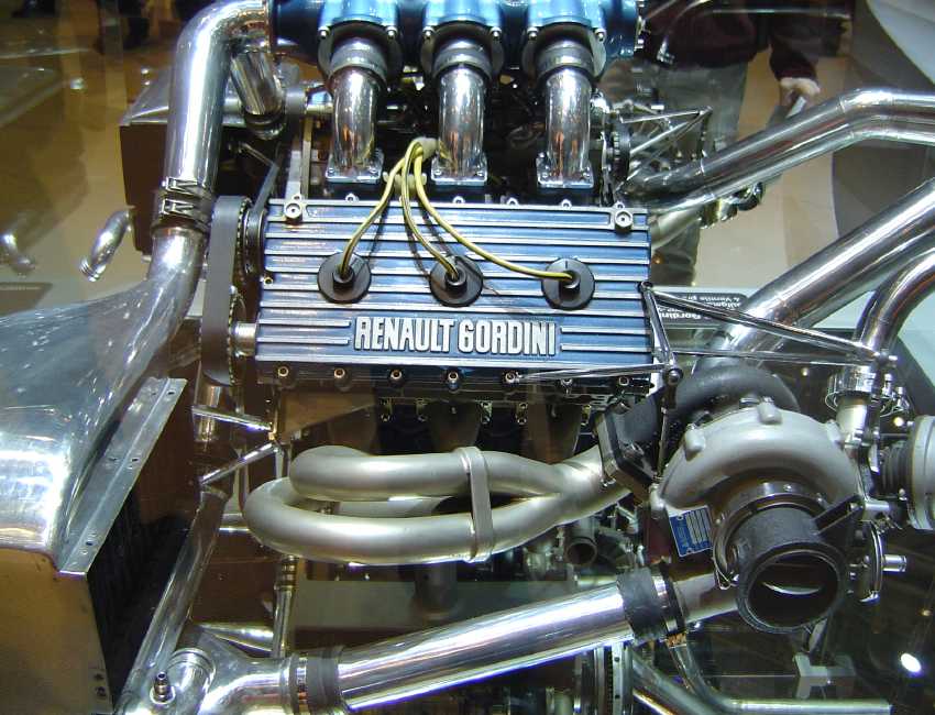 |
Renault first foray into Formula One in 1977, pioneering the turbo-charged engine that would dominate the 1980s -initially the car was so unreliable it was christened the “yellow teapot” by rivals. Renault Gordini turbocharged engine RE20, powered Renault RS01of Jean-Pierre Jabouille on their first race they retired on lap 39 with misfire. Click on picture to get bigger version. |
In Formula One, in the so called "Turbo Era" of 1977 until 1989, engines with a capacity of 1500 cc could achieve anywhere from 1000 to 1500 hp (746 to 1119 kW) (Renault, Honda, BMW, Ferrari and Porsche). Renault was the first manufacturer to apply turbo technology in the F1 field, in 1977 with Renault R01 car and Renault-Gordini turbo engine RE20. The project's high cost was compensated for by its performance, and led to other engine manufacturers following suit.
The first turbocharged car to win a world championship Grand Prix was a Renault, in 1979, fittingly enough at the French GP at Dijon: and the driver was French too, Jean-Pierre Jabouille. Rene Arnoux, in the other Renault, was third after a thrilling battle with Gilles Villeneuve to complete a great day for the French team. Jabouille won one more race for Renault in 1980 before being replaced by Alain Prost, who had even more success, winning nine races: Arnoux won four. Renault left F1 after the 1985 season, returning in 2002.
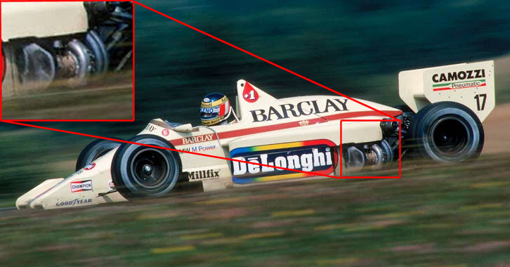 |
Gerhard Berger driving for Barclays Arrows BMW, Arrows A8 - BMW M12 1.5 L4t, Austrian Grand Prix 1985 , Österreichring (Retired). In this time positioning of the turbo unit was free. |
The turbocharged engines took over the F1 field and ended the Ford Cosworth DFV era in the mid 1980s. However, the FIA decided that turbochargers were making the sport too dangerous due to the ridiculous power and speed they were generating and cost. In 1987 FIA decided to limit the maximum boost pressure before the technology was banned completely for 1989.
In Rallying, turbocharged engines of up to 2000 cc have long been the preferred power source for the World Rally Car (WRC) competitors, due to the exceptional power-to-weight ratios. This combines with the use of vehicles with relatively small body shells for maneuverability and handling. As turbo outputs rise to similar levels as the F1 category, the FIA rather than banning the technology enforced a restricted turbo inlet diameter to 34 mm.
Basic Theory
The advantage of turbocharging is clear - instead of wasting thermal energy through exhaust, we can make use of such energy to increase engine power by directing exhaust gas to rotate a turbine, which drives another turbine to pump fresh air into the cylinders resulting in a greater mass of air (Oxygen) entering the cylinders on each intake stroke. A small capacity engine can deliver power comparable with much bigger opponents.
Turbochargers are a type of forced induction system. They simply compress the air flowing into the engine. A turbocharged engine produces more power overall than the same engine without the charging. Objective is to improve the engine's volumetric efficiency by solving one of its limitations. A naturally aspirated car engine uses only the downward stroke of a piston to create an area of low pressure in order to draw (pull) air into the cylinder through the intake valves. Because the pressure in the atmosphere is no more than 1 atm, there ultimately will be a limit to the pressure difference across the intake valves and thus the amount of airflow entering the combustion chamber. Because the turbocharger increases the pressure at the point where air is entering the cylinder, a greater mass of oxygen will be pushed and squeezed in as the inlet manifold pressure increases and more air means that more fuel can be added.
The additional air flow makes it possible to maintain the combustion chamber pressure and fuel/air load even at high engine revolution speeds, increasing the power-to-torque ratio and power-to-weight ratio for the engine. A turbo can significantly boost an engine's horsepower without significantly increasing its weight, which is the huge benefit that makes turbos so popular!
 When people talk about race cars or high-performance sports cars, the topic of turbochargers usually comes up. But turbochargers are also very common, and today, almost must-have on large diesel engines.
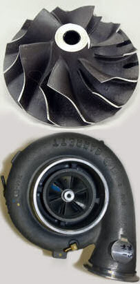
The turbocharger is bolted to the exhaust manifold of the engine. The exhaust from the cylinders passes through the turbine blades, causing the turbine to spin. The more exhaust that goes through the blades, the faster they spin. The turbine is connected by a shaft to the compressor, which is located between the air filter and the intake manifold. The compressor pressurizes the air going into the cylinders. The compressor is a type of centrifugal pump. It draws air in at the center of its blades and flings it outward as it spins.
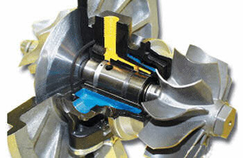
Turbine Bearings
 |
Turbocharger shaft with oil bearing in the middle. You can clearly see the holes where oil enter and exit bearing area. |
The turbine in the turbocharger spins at speeds of up to 150,000 rotations per minute (RPM), that's about 25-30 times faster than most car engines can go. And since it is hooked up to the exhaust, the temperatures in the turbine are also very high.
In order to handle speeds and temperature, the turbine shaft has to be supported very carefully. Most bearings would explode at speeds like this, so most turbochargers use a fluid (oil) bearing. Usually is same lubrication oil engine use for internal lubrication. Just like your crankshaft, you turbo spins on a thin film of oil sandwiched between a set of sliding bearings. This serves two purposes: circulation of oil cools the shaft and some of the other turbocharger parts, and it allows the shaft to spin without much friction. And as we know, any reduction in friction results in a huge increase in efficiency.
 |
Turbocharger with ball bearing center cartridge design |
The introduction of new technology ball bearing center cartridges has given way to smaller frame turbos with capabilities of midsized standard oil bearing counter parts. Instead of a strip of metal, the ball bearing center cartridge design allows the shaft to rotate along tiny precision ball bearings, far cousins of bearings found in skateboard wheels. But these are not your regular ball bearings. They are super-precise bearings made of advanced materials to handle the speeds and temperatures of the turbocharger. They allow the turbine shaft to spin with less friction than the fluid bearings. They also allow a slightly smaller, lighter shaft to be use. This helps the turbocharger accelerate more quickly, further reducing turbo lag.
This way, you can choose a large compressor wheel that can be matched to a disproportionately smaller turbine wheel. Ball bearing turbos are especially beneficial in an application that requires high response, for example in racing, because the increase in peak effective boost is not as apparent as the spool up rate. This means that you can reach peak boost faster, increasing the amount of mid range power.
The biggest factor of concern between standard oil bearing and ball bearing turbos is the cost. This is where the rule of "you want to play, then you got to pay" comes in. Price of ball bearing turbo is double (or more) of the price of an oil bearing turbo. On top of that, ball bearing cartridges are so expensive to service, you just don't do it. You either have to buy a new center assembly or buy a new turbo. As you can see, there's a give and take to everything.
Wastegate
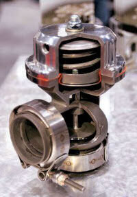 |
Cutout of wastegate valve |
Without a wastegate, the amount of boost that a turbocharger creates varies with the pressure of the engine's exhaust. This happens because exhaust pressure varies with relation to the engine's speed (measured in RPM's). This implies that as an engine reaches higher RPM's, increasing amounts of boost will be created by the turbocharger. The problem with this is that an engine can only accommodate a given amount of boost. Most stock engines are only meant to take about 10 PSI if not less. In order to regulate the amount of boost that comes into the engine, a wastegate acts as a door, only allowing a given amount of exhaust to hit the turbocharger's exhaust turbine, and the rest to bypass the turbine blades, or in some cases to be ventilated in to atmosphere. Once the engine starts producing more exhaust pressure then the wastegate system will allow, a flap is opened to redirect excess exhaust away from the turbine blades. In turn, this is where a wastegate gets its name. It's a gate to carry away waste. In order to regulate when a wastegate opens, a boost controller can be used.
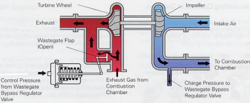
Most automotive turbochargers have a wastegate, which allows the use of a smaller turbocharger to reduce lag while preventing it from spinning too much. The wastegate senses the boost pressure and if the pressure gets too high, it could be an indicator that the turbine is spinning too quickly, so the wastegate bypasses some of the exhaust around the turbine blades, allowing the blades to slow down to proper speed. The introduction of electronic boost control in the late 80s took a great step forward from mechanical wastegate. While mechanical wastegate just set the upper limit of boost pressure, Electronic Boost Control governs the boost pressure throughout the whole rev range. For example, it may limit the boost to 1.4 bar for below 3,000 rpm, then 1.6 bar for 3,000 to 4,500 rpm and then 1.8 bar for over 4,500 rpm. This helps achieving a linear power delivery and contributes to refinement.
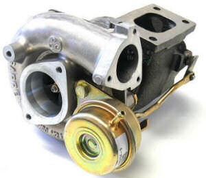 |
Garrett GT28R with internal wastegate and visible actuator |
 |
Wastegate installed next to turbocharger with vent straight out and into the atmosphere |
Basically, Electronic Boost Control is just a wastegate activated by engine management system.
There are two types of wastegate. The first one is an internal wastegate. An internal wastegate is a component on the turbo unit itself. The gate is opened via an actuator which is a diaphragm type system (see left picture). Excess exhaust is then fed directly into the exhaust system after turbine.
We also have what is called an external wastegate, unlike an internal wastegate, it is separate from the turbo unit and does not require an actuator. Excess exhaust can either be fed into the exhaust system or it can be vented straight out and into the atmosphere (see left picture). High performance set-ups typically follow the latter alternative. Most stock systems come with an internal wastegate as this set-up is better suited for low boost applications. However most aftermarket systems perform better with a separate external wastegate assembly making it an ideal choice for those generating boost in the range of 20-30 PSI.
Wastegate in modern V6 Formula 1 engine (post 2014) most of the time will not be open because open wastegate would dump energy that can otherwise be recovered by the MGU-H (the motor generator unit connected to the turbo). Open wastegate drops overall thermal efficiency which the engine manufacturers are trying to maximise.
 |
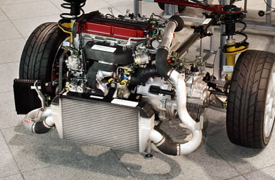
|
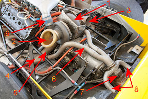
1 - the turbine/compressor unit behind the engine |
On this picture you can see configuration of an turbocharged Cosworth DFX engine fitted o John Barnard's 1979 Chaparral 2K Indycar. |
Confusion about waste gate and blow off valves
Turbo wastegates and blow off valves are two totally different devices with the similar function, and are usually confused. They are fitted on the opposit sides of the turbocharger, and both have a function of relieving excess pressure. Blow-off valves are mounted on the pressure intake side (air side) and the purpose of the valve is to vent off excess pressure of the compressed air when the throttle is shut, but turbo is still pumping the air in to high rate. It just dumps the excess air in to the atmosphere or you can dump the air back into the turbine air intake. Where as a wastegate, as explained before, is mounted on the exhaust side and the valve controls the amount of exhaust going into the turbine thus regulating boost pressure. Max venting of the exhaust via the wastegate is achieved when the max boost is exceeded.
Twin Turbo
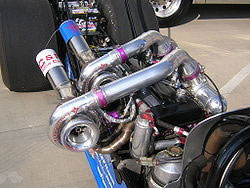 |
Pair of turbochargers on inline 6 engine 2JZ-GTE Toyota Supra fitter on dragster |
Turbo lag can be greatly reduced by use of twin turbo configuration. Most twin-turbo engines have the turbochargers arranged to operate independently, each serves one bank of V- engine cylinders, or even – odd cylinders on inline engines. Turbines can be smaller (with smaller turbo lag) because they have to supply air to smaller number of cylinders. This is so-called "Parallel Twin-Turbo".
An alternative arrangement, "Sequential Twin-Turbo", was designed to improve response and further reduce turbo lag. The turbos operate sequentially, that is, at low speed, all the limited amount of exhaust gas is directed to drive smaller turbine, leaving another turbine idle on low RPM-s. Therefore the first turbine will accelerate quickly reducing the lag. When the exhaust flow reaches sufficient amount to drive both turbos, the second turbo usually bigger, intervenes and helps reaching the maximum boost pressure. Unfortunately, sequential twin-turbo requires very complicated piping. Exhaust pipes from either V-engine banks, or even – odd cylinders on inline engines, should reach both turbos. So do the intake pipes from both banks), thus "Sequential Twin-Turbo" is now losing interest from car makers.
Variable Turbine Geometry
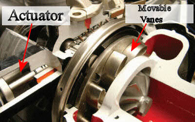
A Variable Turbine Geometry turbocharger is also known as a variable geometry turbocharger (VGT), or a Variable Nozzle Turbine (VNT). Variable Turbine Geometry technology is the next generation in turbocharger technology where the turbo has little movable vanes which can direct exhaust flow onto the turbine blades and is capable to alter the direction of exhaust flow to reduce turbo lag at low engine speed, but it is also used to introduce EGR (Exhaust Gas Recirculation) to reduce emission in diesel engines. This technology is commonly used in turbo diesel engines in recent years.
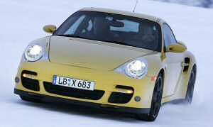 |
First production petrol turbocharged car, Porsche 997 911 Turbo, 2007 |
VTG has been used extensively in turbo diesel engines since the 1990s, but it has never been on a production petrol turbocharged car before until the new 997 Porsche 911 Turbo. This is because the exhaust gas of gasoline engines could reach up to 950°C, versus 700-800°C in diesel engines. Ordinary materials and constructions are difficult to withstand such temperature reliably. The 997 911 Turbo uses a BorgWarner VTG turbocharger which uses special materials derived from aerospace technology, hence solving the temperature problem.
An electronically controlled actuator can adjust the angle of these vanes. The angle of the vanes varies throughout the engine RPM range to optimize turbine behavior. Ordinary turbochargers cannot escape from turbo lag because at low engine rpm the exhaust gas flow is not strong enough to push the turbine quickly. This problem is especially serious to modern diesel engines, because they tend to use big turbos to compensate for their lack of efficiency.
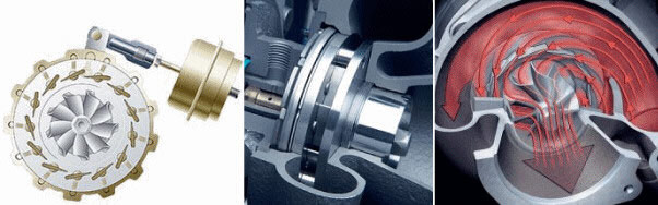 |
In cut-through picture, you can see the direction of exhaust flow when the variable vanes are in an almost closed angle. This position is optimized for low engine RPM speeds, pre-boost. The narrow passage of which the exhaust gas has to flow through accelerates the exhaust gas towards the turbine blades, making them spin faster. The angle of the vanes also directs the gas to hit the blades at the proper angle. |
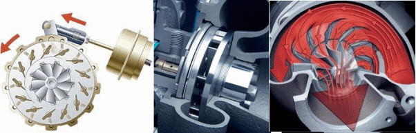 |
Above is when at high rpm the exhaust flow is strong enough. The variable turbine vanes are fully opened to take advantage of the high exhaust flow. The high exhaust flow at high engine speeds are fully directed onto the turbine blades. This also releases the exhaust pressure in the turbocharger, saving the need of wastegate. |
Intercoolers
With air being pumped into the cylinders under pressure by the hot turbocharger, and then being further compressed by the piston, there is more danger of knocking. Knocking happens because as you compress air, the temperature of the air increases. The temperature may increase enough to preignite the fuel before the spark plug fires. Cars with turbochargers often need to run on higher octane fuel to avoid knock. If the boost pressure is really high, the compression ratio of the engine may have to be reduced to avoid knocking.
An intercooler is a simple heat exchanger (actually, not so simple!). That means there are two or more fluids that don't physically touch each other but a transfer heat or energy takes place between them. Some early production cars around came with intercoolers to cool down the hot compressed air coming from the turbocharger. Some of them where using outside air as the cooling media and some where using water. Drag racers often use ice in the water to increase cooling effect.
At wide open throttle and full boost the hot compressed air coming from a turbocharger is probably between 100 and 250°C depending on the particular turbo, boost pressure, outside air temperature, etc. We want to cool it down, which reduces its volume so we can pack more air molecules into the cylinders and reduce the engine's likelihood of detonation.
How does an intercooler work? Hot air from the turbo flows through tubes inside the intercooler. The turbo air transfers heat to the tubes, warming the tubes and cooling the turbo air. Outside air (or water) passes over the tubes and between fins that are attached to the tubes. Heat is transferred from the hot tubes and fins to the cool outside air. This heats the outside air while cooling the tubes. This is how the turbo air is cooled down. Heat goes from the turbo air to the tubes to the outside air.
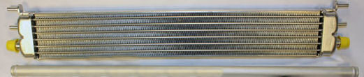
 |
Intercooler system fitted on Mitsubishi Lancer Evolution IX. |
Another aspect of intercoolers to be considered is pressure drop. The pressure read by a boost gauge (if you have one) is the pressure in the intake manifold. It is not the same as the pressure that the turbocharger itself puts out. To get a fluid, such as air, to flow from A to B there must be a difference in pressure from one end to the other. For example, one vendor's catalog implies that if you had little or no pressure drop then you would have no heat transfer. This is incorrect. Pressure drop and heat transfer are relatively independent, you can have good heat transfer in an intercooler that has a small pressure drop if it is designed correctly. It is easier to have good heat transfer when there is a larger pressure drop because the fluid's turbulence helps the heat transfer, but modern and good quality intercoolers can have less than 0.2 psi of drop while flowing a heck of a lot more air, so it is certainly feasible.
With or without intercooler? If is properly designed and calculated for your layout, intercooler can increase the power of engine for 10 to 20%.
And on the end a question: Turbo and non-turbo versions of the same engines... what’s the power gain of fitting a turbo?
Well, when there are factory naturally aspirated and turbo versions available to directly compare with one another, the turbo engines tend to make something like 30-40 % more power.
Of course, in the aftermarket, people bolt on turbos that cause the engine to develop 100%, 200% – sometimes even more power. But they never do so with factory drivebility or reliability.
So, keeping it within the boundaries of good on-road performance across most of the rev range, and good reliability without having to replace all the internals of the engine after each trip to local supermarket, you might say that a 50 % power increase over the naturally aspirated figure is an achievable and realistic turbo goal.
There are many trade-offs involved in turbochargers for an engine.
Turbo Lag
 One of the main problems with turbochargers is that they do not provide an immediate power boost when you “pedal to the metal”. It takes a second or two for the turbine to get up to speed before full pumping of the air is produced. This results in a feeling of lag when you step on the gas, and then the car lunges ahead when the turbo gets right speed. Turbo lag ruins the refinement of a car very much, and was really the biggest problem preventing the early turbo cars from being accepted as practical. This problem modern Formula 1 will try to fight with ERS-H turbine/motor/generator combo.
Although turbocharging had been extensively and successfully used in motor racing - started from BMW 2002 turbo and then spread to endurance racing and eventually
Formula One - road cars always require a more user-friendly power delivery. Contemporary turbines were large and heavy, and can not start spinning until about 3,500 or more RPM of engine speed. As a result, low-speed output remained weak. Besides, since the contemporary turbocharging required compression ratio to be decreased to about 6.5:1 in order to avoid overheat to
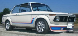 |
BMW 2002 turbo , 1974 |
cylinder head, the pre-charged output was even weaker than a normally-aspirated engine of the same capacity in that RPM range!
Turbo lag can cause trouble in daily driving. Before the turbo intervenes, the car performs like an ordinary sedan. Open full throttle and raise the engine speed, counting from 1, 2, 3, 4.... suddenly the power surge at 3,500 rpm and the car becomes a wild beast. On wet surfaces or tight bends this might result in wheel spin or even lost of control. In the presence of turbo lag, it is very difficult to drive a car fluently.
One way to decrease turbo lag is to reduce the inertia of the rotating parts, mainly by reducing their weight. This allows the turbine and compressor to accelerate quickly, and start providing boost earlier. To handle the tremendous heat in exhaust flow, turbines are mostly made of stainless steel or ceramic (the latter is especially favored by the Japanese IHI). Occasionally there are some cars employ titanium turbines, which is even lighter but very expensive. Modern ceramic or titanium turbine blades are lighter than the steel blades used in most turbochargers. Again, this allows the turbine to spin up to speed faster, which reduces turbo lag.
Another sure way to reduce the inertia of the turbine and compressor is to make the turbocharger smaller. A small turbocharger will provide boost more quickly and at lower engine speeds, but because of their diameter may not be able to provide much boost at higher engine speeds when a really large volume of air is going into the engine. It is also in danger of spinning too quickly at higher engine speeds, when lots of exhaust is passing through the turbine.
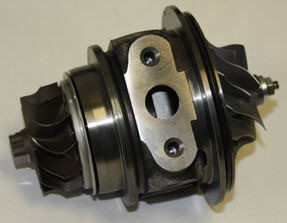 |
Garett turbo rotor assembly |
As we sad before, some turbochargers use ball bearings instead of fluid bearings to support the turbine shaft. They allow the turbine shaft to spin with less friction. They also allow a smaller shaft to be used. This helps the turbocharger accelerate more quickly, further reducing turbo lag.
The first “practical” turbocharged road car eventually appeared in 1975, that’s the Porsche 911 Turbo 3.0. To reduce turbo lag, Porsche engineers designed a mechanism allowing the turbine to "pre-spin" before boosting. The secret was a recirculation pipe
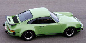 |
Porsche 911 Turbo 3.0 |
and valve: before the exhaust gas attains enough pressure for driving the turbine, a recirculation path is established between the fresh-air-charging turbine's inlet and outlet, thus the turbine can spin freely without slowing down by boost pressure. When the exhaust gas becomes sufficient to turbocharge, a valve will close the recirculation path, then the already-spinning turbine will be able to charge fresh air into the engine more quickly. Again, turbo lag is greatly reduced while power transition becomes smoother.
During the 80s, turbocharging continued to evolve for better road manner. As the material and production technology improved, turbine's weight and inertia were greatly reduced, hence improved response and reduce turbo lag a lot.
Other cause of the turbocharger inefficiency comes from the fact that the power to spin the turbine is not free. It is always same story, if you want something, you have to give something. Having a turbine in the exhaust flow increases the restriction in the exhaust. This means that on the exhaust stroke, the engine has to push against a higher back-pressure. This subtracts a little bit of power from the cylinders that are firing at the same time.