F-Duct or Rear Blown Wing
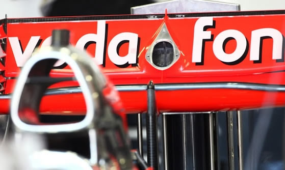
Days before the first Grand Prix of the 2010 season, McLaren's MP4/25 grew an air inlet on top of the chassis. It turned out to be a feeder for its F-Duct system. The actual name for McLaren's so called 'F-Duct' is the 'RW80'. It is believed the F-Duct name was created by the specialist media, either in reference to the mere shape and appearance of the air inlet, or the fact it was mounted on the red 'f' of the upper monocoque "Vodafone" branding.
'RW80', however, is the official name for the rear wing stalling system, with McLaren describing its innovations with an acronym (Rear Wing) following by a number based on iterations. Initially, some insiders jokingly tried to start a trend when the controversy broke by describing it as the Formula 1 'kneegate', referring to the way in which the McLaren driver's trigger the airflow. Red Bull's Christian Horner joked in Shanghai: "We call it the F'ing (F…ing) duct."
Sebastian Vettel, RBR driver, said in China: "This morning I had a good opportunity to see it at work myself, when I was running behind Jenson." "In the middle of the straight he just left me, as if I was standing still," said the German.
Throughout the history of Formula 1 the genius designers and arguably the best engineers money can buy, have found ways around the FIA regulations to gain an advantage. Last season we saw the Brawn GP's rear diffuser and this season is no different with McLaren's F-Duct (blown rear wing) and RedBull's RB6 blown diffuser.
But what is the F-Duct and how does it work?
When McLaren's F-Duct system first appeared in pre-season testing it was hailed by many as a true stroke of genius, a classic example of out-thinking the regulations. With the basic idea being that the driver with his sole movement is able to alter the airflow over the rear wing, without infringing regulation 3.15, and in doing so gain a speed advantage on straights.
For beginning let's see what about these regulations. ![]()
I will list all important paragraphs related to paragraph 3.15 so you will have full picture.
3.15 Aerodynamic influence:
With the exception of the cover described in Article 6.5.1 (when used in the pit lane), the driver adjustable bodywork described in Article 3.18 and the ducts described in Article 11.4, any specific part of the car influencing its aerodynamic performance :
- must comply with the rules relating to bodywork;
- must be rigidly secured to the entirely sprung part of the car (rigidly secured means not having any degree of freedom);
- must remain immobile in relation to the sprung part of the car.
Any device or construction that is designed to bridge the gap between the sprung part of the car and the ground is prohibited under all circumstances.
No part having an aerodynamic influence and no part of the bodywork, with the exception of the skid block in 3.13 above, may under any circumstances be located below the reference plane.6.5.1 A cover must be fitted over any refuelling connector at all times when the car is running on the track. The cover and its attachments must be sufficiently strong to avoid accidental opening in the event of an accident.
3.18 Driver adjustable bodywork:
A single closed section situated each side of car centre line in the volume bounded by:
- lines 450mm and 800mm in front of the front wheel centre line ;
- a vertical plane which intersects these lines at a distance 250mm from the car centre line;
- and the inboard face of the bodywork described in Article 3.7.5;
is allowed to change incidence while the vehicle is in motion within a maximum range of 6°, provided any such change maintains compliance with all of the bodywork dimensional regulations.
Alteration of the incidence of these sections must be made simultaneously and may only be commanded by direct driver input and controlled using the control electronics specified in Article 8.2. Except when the car is in the pit lane, a maximum of two adjustments may be made within any single lap of a circuit.11.4 Air ducts:
Air ducts around the front and rear brakes will be considered part of the braking system and shall not protrude beyond:
- a plane parallel to the ground situated at a distance of 160mm above the horizontal centre line of the wheel;
- a plane parallel to the ground situated at a distance of 160mm below the horizontal centre line of the wheel;
- a vertical plane parallel to the inner face of the wheel rim and displaced from it by 120mm toward the car centre line.
Furthermore:
- when viewed from the side the ducts must not protrude forwards beyond a radius of 330mm from the centre of the wheel or backwards beyond a radius of 180mm from the centre of the wheel ;
- the ducts may not rotate with the wheels nor may they, or any of their mountings, protrude axially beyond the outer face of the wheel fastener;
- no part of the car, other than those specifically defined in Articles 12.8.1 and 12.8.2, may obscure any part of the wheel when viewed from the outside of the car towards the car centre line along the axis of the wheel.
All measurements will be made with the wheel held in a vertical position.3.7.5 Ahead of the front wheel centre line and between 750mm and 840mm from the car centre line there must be bodywork with a projected area of no less than 95,000mm in side view.
8.2 Control electronics:
8.2.1 All components of the engine, gearbox, clutch, differential and KERS in addition to all associated actuators must be controlled by an Electronic Control Unit (ECU) which has been manufactured by an FIA designated supplier to a specification determined by the FIA.
The ECU may only be used with FIA approved software and may only be connected to the control system wiring loom, sensors and actuators in a manner specified by the FIA.
8.2.2 All control sensors, actuators and FIA monitoring sensors will be specified and homologated by the FIA.
Each and every component of the control system will be sealed and uniquely identified and their identities tracked through their life cycle.
These components and units may not be disassembled or modified in any way and seals and identifiers must remain intact and legible.
8.2.3 The control system wiring loom connectivity will be specified by the FIA.
8.2.4 Pneumatic valve pressure may only be controlled via a passive mechanical regulator or from the ECU and its operation will be monitored by the ECU.
8.2.5 The car hydraulic system will be monitored by the ECU.
8.2.6 The ECU will be designed to run from a car system supply voltage of 12V nominal provided by a homologated voltage regulator.
McLaren was smart enough to use driver movement as the switch to alter air flow, and driver is not an aerodynamical device, otherwise it will contravene FIA regulation and paragraph 3.15.
Basic wing theory
(if you want to know more, check my articles about angle of attack, Bernoulli equation, boundary layer, drag, stall and wings)
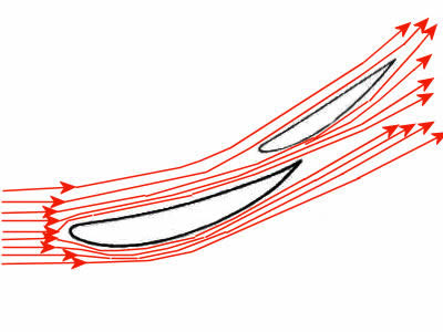
First we need to look at some basic aerodynamic theory regarding wing profiles and lift/drag ratios. At the simplest level a wing generates downforce due to its profile accelerating airflow on its lower surface in relation to the flow over the top surface.
If flow is accelerated pressure drops, with the result being a pressure differential between the upper and lower surface of the wing and thus a net downward force, as illustrated below.
Flaps and slot gaps
If the angle of attack of a wing is increased it can ultimately 'stall' due to flow separation along the trailing edge, with a resultant loss in downforce and consequently aerodynamic grip.
The above picture shows airplane wing stalling, however the basic theory is the same for a downforce generating racecar wing.
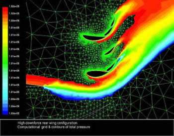
In the nineties teams can use unlimited number of wing elements and flaps. Here is the picture of CFD simulation of such rear wing
To get around this problem, dual element or slot-gap wings are used, these allow for some of the high pressure flow from the top surface of the wing to bleed to the lower surface of the next flap energizing the flow. This increases the speed of the flow under the wing, increasing downforce and reducing the boundary flow separation. If you look at a F1 rear wing few years ago, you can see this concept taken to the extreme, with multi-element wings creating huge amounts of downforce.
The downside being a significant drag penalty. However if the flow over the 'flap' section of the wing can be stalled, the lift/drag ratio worsens, but the overall result is a massive drop in the coefficient of downforce, resulting in a net reduction in drag, and the big benefits in relation to top speed. It should however be noted that it is only stalling the trailing edge flow that is beneficial as opposed to stalling the entire wing.
How it was done before
When stalling aerodynamics there are two possible benefits. Reducing drag for more top speed or reducing downforce.
If you stall the flap on an F1-wing (in the wind tunnel) then the drag drops enough to calculate that the top-speed of the car could be 3-7 kmh faster but the trick is doing it in a way that's legal, or better to say not illegal. Wind tunnel engineers can do this by altering the slot-gap geometry and/or changing parts to simulate flexing on the track. It's very easy to demonstrate this in a wind tunnel - just very difficult to engineer it so that it's not illegal.
Previously, teams created flexible wing sections which allowed the 'slot gap' to close up under high aerodynamic loads and stall the wing. Once this became evident to the governing bodies it was rapidly outlawed. Wings are now subject to static load tests to ensure that they cannot flex.
So if a team were able to achieve a similar effect within the regulations, considerable straight-line performance gains could be made.
And there is a solution
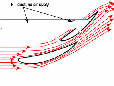
McLaren have found a very neat solution for redirecting the airflow over the rear wing and consequently allowing the flap to stall. Whilst they have been very tight lipped about the system, it is most likely that the conduit from the front to rear of the car has a vent in the cockpit that can be blocked by the driver left leg, which is not in use on long straights. Blocking the vent could direct enough airflow through the conduit leading to the rear wing upper flap with build in horizontal opening slots. If you blow additional air trough this slot, this will disrupt the flow over the rear flap and induce a stall. This approach is ingenious for two key reasons:
- By using the driver's leg to direct the flow, the regulations are not contravened regarding movable aerodynamic devices.
- By incorporating the design into the monocoque it becomes very difficult for other teams to copy the device, due to the fact monocoques have to be homologated before season and changes are very expensive to make.

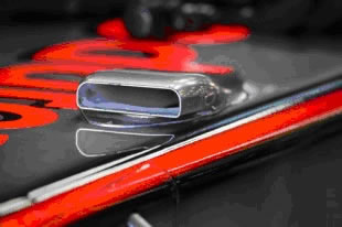
During the preseason testing McLaren sported a little airscoop in the front of the car, claiming that only use of this snorkel is cooling of the power steering rack, hydraulic lines, electronics boxes and driver. As McLaren continue to use testing rigs to map their cars aerodynamics, the importance of the scoop on the top of the chassis is becoming apparent.
On Friday the car lapped with an array of sensors attached to the rear wing. However, there was an additional sensor mounted inside the snorkel, raising the question why would you want to test rear wing and driver cooling device simultaneously?
However the initially simple inlet has been upgraded by at least two more shapely snorkel-like derivatives, each with an apparently unnecessarily complex double wall construction creating smooth narrow inlet and a streamlined outer surface. This snorkel has been always present despite the cold and wet testing sessions, suggestion its purpose goes beyond a simple primary purpose of cooling.
 In this time only a rumor around the internet suggests the inlet is linked by a duct to the shark fin and blown rear wing. At first appearing to be simply a wild rumor, that the snorkel is blocked by the driver's knee to alter the rear wing airflow. However the presence of the airflow sensor along with the rear wing test rig, suggests there might be a link after all. The rumors suggest the driver's left braking leg, which sits unused on long straights, could be used to alter the flow from the snorkel to the rear wing duct, where a valve alters flow through the blown slot to stall the rear wing. This would reduce downforce and also drag, which would allow a higher top speed. Then the driver moves his leg to start to brake for the next turn the valve switches airflow back to normal, the wings airflow reattaches and provides the downforce needed for the turns.
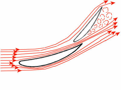
As added note, it is worth noticing that such blowing slot in the flap can be used in two ways. One is adding the flow and other is stalling the flow over the wings surface. How the slot creates these two very different effects depends on the slots angle to the wings surface.
To aid the airflow, you need a slot blowing nearly inline with the surface and airflow. Known as Tangential flow, this flat entry angle creates a relatively wide slot when viewed externally.
To stall the airflow, you need a slot blowing at near right angles to the surface. This creates a narrow slot when viewed externally.
Looking at what you need to aid or stall the airflow also requires different placement of the slot.
So, after all, how F-Duct work and why is beneficial to use it on the car?
 |
Modern F1 wing with proper and attached air stream around it |
|
Modern F1 wing with air stream detached and stalled due to high angle of attack |
For an F1 car the rear wing creates around a third of the cars downforce. But running at high speed the drag from the rear wing is tremendous. Anything that reduces the drag of the rear wing will aid top speed. If this can be done in a non linear way (ON/OFF), that is; high downforce/drag at lower speeds increasing towards top speed and then less drag only at speeds where car is in a straight line and doesn't need downforce, then lap times will show an improvement.
As airflows over the surface of a wing increase, or angle of attack is bigger, it has a tendency to slow down and separate from the wing. Particularly underneath the wing which runs at a lower pressure than the top surface. This separation initially reduces efficiency by adding drag to the wing, before the airflow totally breaks up and the wing stalls. What is very important in F-Duct case is that when a wing stalls the wing loses most of its downforce and most importantly the drag.
The steeper a wings angle, the greater chance of separation.
To combat this, aerodynamicists need to speed up and energize the flow near the wings lover surface. To do this they split the wing into separate elements (flaps) and this creates a slot. Trough the slot they send high pressure air from above the wing to the area underneath the flap which then speeds and energize the local flow underneath the wing. The more slots the steeper the wing can run.
In the nineties teams can use unlimited number of elements (flaps). Slowly the rule makers sought to reduce the wings potential for downforce and reduced the number of elements (defined as 'closed sections' within the rules), initially to four then three and currently two. Modern rear wings are made up to two elements, a main plane (the forward and mostly bigger section of wing) and a flap (which sits behind it). That mean that wing is intended only to have a single slot and hence only one place to speed up the flow under the upper wing element.
Previously teams have sought to use the wing stalling to gain top speed (from the reduced drag). By flexing the wings at higher speed, the wings move to create smaller slot gaps, with this reducing the feed on lover part of next flap and this leads to the wings stalling. The FIA has acted with both load tests and in the past few years with slot gap separators to prevent this practice. Slot gap separators are now mandated for the rear wing, and appear as a plate fitted around the profile of the two wing elements to prevent them moving.
 The McLaren 2010 wing uses a slot in the back side of the flap (not the main plane), this time fed by scoop in the front of the driver and trough the shark fin. The snorkel on the top of the chassis feeds a duct passing down inside the foot well, its position is somewhere around the pedals, most probably it runs down alongside the brake pedal/footrest so as to avoid the mandatory padding inside the cockpit.
This duct has a 'hole' in it to 'cool' the driver inside the cockpit. However, the duct continues inside the monocoque, past the fuel tank and up and over the airbox (probably passing by the hatch fitted high up on the engine cover), then through the shark fin and into the rear wing flap.
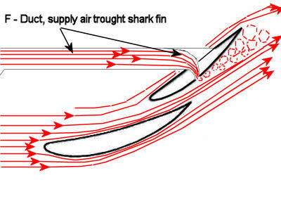 When the driver places his knee over the 'hole' the flow is diverted from cockpit "cooling" into the rest of the duct and this feeds the slot on the rear wing flap. There is enough airflow and pressure through the convoluted duct to disrupt the airflow under the rear of the wing, effectively breaking up the flow around the wing. This is what F1 aerodynamicists term a 'stalled' condition, although this is different to the term 'stall' used in aeronautical aerodynamics. As an F1 wing is so highly loaded, the majority of its drag is from trailing vortices, stalling the flow under the wing reduces these vortices and their inherent drag.
In this 'stalled' state, the strong spiraling flows coming off the wing, that lead to the huge drag penalty at highly loaded F1 wing incurs, break up. Without these flows and their resulting drag penalty, the car is able to get to a higher top speed, by around 3-7kmh.
 When the driver is ready to brake for the next corner, he releases knee from the hole and the airflow passes back into the cockpit and the rear wing flow reattaches, creating downforce and its attendant drag. In this configuration the car can lap normally with its wings delivering maximum downforce.
This set-up is legal as the rear wing slot itself is legal (used by McLaren, BMW Sauber last year).
There is no specific working to prevent wing stalling in the rules. There are no moving aerodynamic parts, except perhaps for the drivers foot/leg/knee/hand. It's a piece of interpretive genius, but perhaps as far removed from the spirit of the rules as you can get.
Of course, this device is deemed legal; teams can either formally protest it or adopt it themselves. Doing the latter is possible for most teams, as they have apertures in the foot well area to fit a snorkel, while the shark fin and rear wing are easily created.
But, finding a route for the duct out of the tub is proving the headache, as the monocoque may not have any openings sufficiently large enough. This year the monocoque is subject to homologation and hence cannot be altered until the 2011 season. Of course 'where there's a will, there's a way', teams don't want to lose a straight line speed advantage.
 And as most teams were forced to incorporate the season’s two must have gizmos – the drag reducing F- Duct rear wing and the exhaust blown diffuser, they needed all the practice time they could get. These were complicated aerodynamic devices which tested the best engineers in F1 to the limit.
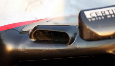
Already in the first race of the season, on the prerace testing Sauber prepared their own version of the F duct for testing. Perhaps ex-McLaren test driver Pedro De La Rosa brought some ideas to the team. We can see that the left hand sidepod has an inlet moulded into it.
 This presumably feeds air through the sidepod and around the airbox to run into the shark fin. The ducting inside the shark fin is quite evident and ends by connecting to the rear wing. It appears that air feed tube is attach to the main plane (not the flap as with McLarens set up) somewhere behind the existing blown slot inlet.
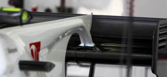
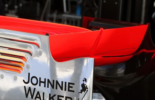
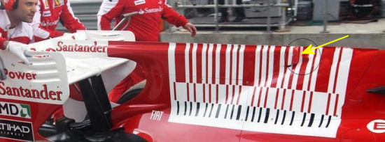
In the first practice for China GP, Ferrari unveiled their new rear wing, which features a blown flap in a similar manner to McLaren. Unlike the McLaren and Sauber set ups, the Ferrari solution does not appear to have the driver interacting with the duct.
Instead the wing was fed with airflow coming from an inlet high up on the engine cover, well away from the drivers reach. In this time no signs of a driver controlled inlet around the cockpit was evident. Ferrari didn't use this device during GP and after the event Alonso sad to Autosport.com "I had nothing inside the cockpit because the system is not complete. We tested the engine cover to compare it with the standard one. I didn't notice anything. I guess there will some new numbers from an aero point of view."
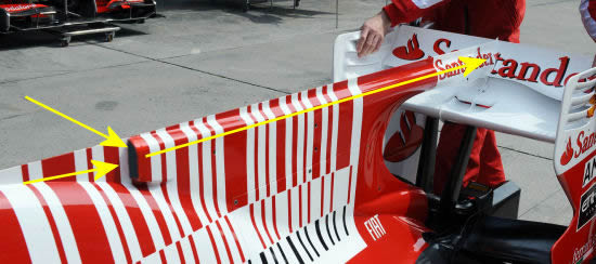
After few weeks Ferrari has presented their fully developed F-Duct system. In principle this is exactly the same as the McLaren version except that the driver's left hand is used to divert the air instead of the knee. Existing cabling duct was used to bring the air in cockpit.
 Renault were late to the F-Duct party, only bringing it to the car at the Belgian Grand Prix, round 13, but were able to make it work straight away. It was among the first of the F-Ducts which stall the wing main plane rather than just the flap.
 The major disadvantages of this being that the driver only has one hand on the steering wheel down the straights. Right hand is commonly used to adjust the brake bias so on some occasions the driver has both hands off the wheel. Though both drivers are skilful enough for such situations, approaching corners at speeds above 150mph start to worry the FIA.
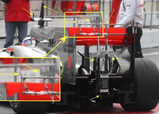
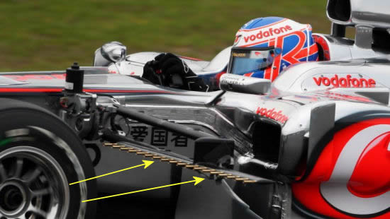
Fittingly, as the team that invented it, McLaren were still developing the F-Duct rear wing right up to the last race. The original design blew the air out of the flap on the wing (see Button drawing), but as the season went on and other teams like Force India, Mercedes, Sauber and Renault found better results from blowing the air out of the main wing element, McLaren tried that too. They first tried it in Suzuka, but struggled to get it working better than the original and that continued until last race of the season in Abu Dhabi, where in Friday practice Lewis Hamilton ran the blown main plane version and Jenson Button ran the original blown flap wing.
Both drivers ended up qualifying and racing the main plane version (see Hamilton drawing). This seems to have had a more powerful effect on straight line speed. But it didn’t help Hamilton much in the race, as he still could not overtake Robert Kubica with his similarly armed Renault.
Today it’s probably easier to compare the F-Duct to the current DRS. In the best cases it probably had about 65% of the effect of the DRS. Presumably because you can’t lose the form drag of the flap as effectively. Today DRS gains about 10-15Km/h and 0.5-0.7s/lap.
A controversial car modification pioneered by McLaren was banned for the 2011 Formula One season after the rest of the teams voted against it. Concerns have arisen about how the feature is operated, with Ferrari and Red Bull version requiring the driver to open and close a hole in the cockpit with his hands, meaning less control over the steering wheel. Rules banned driver controlled aero (excluding DRS), slots in the rear wing and bodywork connecting to the rear wing. Although these approaches banned the driver operated F-Duct, the fluid switch and stalling concepts remain valid and the new generation of Drag Reducing Devices (commonly termed DRD or passive DRS) feature many of the components and concepts of the F-Duct.
McLaren unsuccessfully tried to convince the other teams at a meeting before Sunday's Spanish Grand Prix, won by Red Bull's Mark Webber, that the innovation should not be banned. The Formula One Teams Association take this decision as part of a package of measures that will be forwarded to motorsport's governing body, the FIA, for ratification.
Red Bull boss Christian Horner outlined his opposition to the F-Duct system.
"It is a clever piece of engineering and hats off to the guys who invented it, but some of the solutions this weekend look a bit marginal when you see drivers driving with finger tips and no hands, so I think there is a safety issue and a cost issue to take into account."
Overall, year 2010 was a very interesting year from a technical point of view and next year will be too. Things to watch out for next year are the return of the KERS , an energy regeneration system, giving a boost to the engine power; the adjustable rear wing and FIA things it's a good replacement for F-Duct and will give a good possibilities for overtaking, about which there are some misgivings from the drivers, and the change of tires to Pirelli. We will not see the F Duct again, nor the double diffuser as both have been banned for 2011 season.
World Motor Sport Council decisions:
Driver adjustable bodywork
From 2011, adjustable bodywork may be activated by the driver at any time prior to the start of the race and, for the sole purpose of improving overtaking opportunities during the race, after the driver has completed two laps. The driver may only activate the adjustable bodywork in the race when he has been notified via the control electronics that it is enabled. It will only be enabled if the driver is less than one second behind another at any of the pre-determined positions around each circuit. The system will be disabled the first time the driver uses the brakes after the system has been activated. The FIA may, after consulting all the competitors, adjust the time proximity in order to ensure the purpose of the adjustable bodywork is met.
Aerodynamic influence
With the exception of the parts necessary for the driver adjustable bodywork, any car system, device or procedure which uses driver movement as a means of altering the aerodynamic characteristics of the car is prohibited from 2011.