Wings
First, a small explanation: there is no term ‘wing’, ‘underbody’ or ‘diffuser’ mentioned in the FIA rules. In the FIA Technical Regulations the area of rear wing is called “Bodywork behind the rear wheel centre line“, area of the front wing is called “Bodywork around the front wheels” and "Front bodywork", and underbody or undertray surfaces are called “Bodywork facing the ground”. There is noting about diffuser either. He is part of “Bodywork facing the ground” rules. You can find, however term ‘Gurney flap’.
For example, front wing is not regulated by wings dimension. Rules are giving you only dimensional imaginary “box” where wings (or anything else) are situated, and same apply for rear wings. Wing elements are called “closed section“ and they have regulated number of them, concave radius and chord. Rear wing assembly, as we know, must have only two elements, main wing element and upper flap element, and that's how they are described in the rules:
„- when viewed from the side of the car, no longitudinal cross section may have more than two sections in this area, each of which must be closed.“
Funny, is it!!! Only Formula 1 engineer can understand this!
For few of you curious about this, I will copy here only rules regarding “Bodywork behind the rear wheel centre line“ (FIA Tech regs 2011) so you can see what I’m talking about. If you want to know more, FIA technical regulations are available for download from FIA official site with all of relevant measurements, sizes and positions. Enjoy!
3.10 Bodywork behind the rear wheel centre line :
3.10.1 Any bodywork more than 150mm behind the rear wheel centre line which is between 150mm and 730mm above the reference plane, and between 75mm and 355mm from the car centre line, must lie in an area when viewed from the side of the car that is situated between 150mm and 350mm behind the rear wheel centre line and between 300mm and 400mm above the reference plane. When viewed from the side of the car no longitudinal cross section may have more than one section in this area. Furthermore, no part of this
section in contact with the external air stream may have a local concave radius of curvature smaller than 100mm.
Once this section is defined, ‘gurney’ type trim tabs may be fitted to the trailing edge. When measured in any longitudinal cross section no dimension of any such trim tab may exceed 20mm.
3.10.2 Other than the bodywork defined in Article 3.10.9, any bodywork behind a point lying 50mm forward of the rear wheel centre line which is more than 730mm above the reference plane, and less than 355mm from the car centre line, must lie in an area when viewed from the side of the car that is situated between the rear wheel centre line and a point 350mm behind it.
With the exception of minimal parts solely associated with adjustment of the section in accordance with Article 3.18:
- when viewed from the side of the car, no longitudinal cross section may have more than two sections in this area, each of which must be closed.
- no part of these longitudinal cross sections in contact with the external air stream may have a local concave radius of curvature smaller than 100mm.
Once the rearmost and uppermost section is defined, ‘gurney’ type trim tabs may be fitted to the trailing edge. When measured in any longitudinal cross section no dimension of any such trim tab may exceed 20mm.
The chord of the rearmost and uppermost closed section must always be smaller than the chord of the lowermost section at the same lateral station. Furthermore, the distance between adjacent sections at any longitudinal plane must lie between 10mm and 15mm at their closest position, except, in accordance with Article 3.18, when this distance must lie between 10mm and 50mm.
3.10.3 In order to ensure that the individual profiles and the relationship between these two sections can only change whilst the car is in motion in accordance with Article 3.18, they must be bridged by means of pairs of rigid impervious supports arranged such that no part of the trailing edge of the forward section may be more than 200mm laterally from a pair of supports. These pairs of supports must:
- be located no more than 355mm from the car centre line;
- fully enclose each complete sections such that their inner profiles match that of each section. With the exception of minimal local changes where the two sections are adjacent to each other, their outer profiles must be offset from the inner profiles by between 8mm and 30mm and may not incorporate any radius smaller than 10mm (‘gurney’ type trim tabs may however be fitted between the supports);
- be aligned as a pair so as to provide a bearing across their full thickness and along a profile length of at least 10mm when the distance between the two sections is at its closest position;
- not be recessed into the wing profiles (where a recess is defined as a reduction in section at a rate greater than 45° with respect to a lateral axis);
- be arranged so that any curvature occurs only in a horizontal plane;
- be between 2mm and 5mm thick;
- be rigidly fixed to their respective sections;
- be constructed from a material with modulus greater than 50GPa.
These supports will be ignored when assessing whether the car is in compliance with Articles 3.6, 3.9.2, 3.10.1, 3.10.2, 3.10.4 and 3.10.6.
3.10.4 No part of the car between 75mm and 355mm from the car centre line may be more than 350mm behind the rear wheel centre line.
3.10.5 Any parts of the car less than 75mm from the car centre line and more than 500mm behind the rear wheel centre line must be situated between 200mm and 400mm above the reference plane.
3.10.6 No part of the car less than 75mm from the car centre line and more than 350mm behind the rear wheel centre line may be more than 400mm above the reference plane.
3.10.7 No part of the car more than 375mm from the car centre line may be more than 350mm behind the rear wheel centre line.
3.10.8 In side view, the projected area of any bodywork lying between 300mm and 950mm above the reference plane and between the rear wheel centre line and a point 600mm behind it and more than 355mm from the car centre line must be greater than 330000mm².
3.10.9 Any horizontal section between 600mm and 730mm above the reference plane, taken through bodywork located rearward of a point lying 50mm forward of the rear wheel centre line and less than 75mm from the car centre line, may contain no more than two closed symmetrical sections with a maximum total area of 5000mm2. The thickness of
each section may not exceed 25mm when measured perpendicular to the car centre line.
Once fully defined, the section at 725mm above the reference plane may be extruded upwards to join the sections defined in Article 3.10.2. A fillet radius no greater than 10mm may be used where these sections join.
Ouch!!! That's hurt!!!!
By the way, on some places in section „Bodywork behind the rear wheel centre line“ part of the rules, there is mention of Article 3.18. This part of the rules explain „Driver adjustable bodywork“, or as normal people calling it, adjustable rear wing or „Drag Reduction System (DRS)“. There is no word „wing“ in this part either. Here is copy of the rules, section 3.18:
3.18 Driver adjustable bodywork :
3.18.1 The incidence of the rearmost and uppermost closed section described in Article 3.10.2 may be varied whilst the car is in motion provided :
- It comprises only one component that must be symmetrically arranged about the car centre line with a minimum width of 708mm.
- With the exception of minimal parts solely associated with adjustment of the section, no parts of the section in contact with the external airstream may be located any more than 355mm from of the car centre line.
- With the exception of any minimal parts solely associated with adjustment of the rearmost and uppermost section, two closed sections are used in the area described in Article 3.10.2. Any such variation of incidence maintains compliance with all of the bodywork regulations.
- When viewed from the side of the car at any longitudinal vertical cross section, the physical point of rotation of the rearmost and uppermost closed section must be fixed and located no more than 20mm below the upper extremity and no more than 20mm forward of the rear extremity of the area described in Article 3.10.2 at all times.
- The design is such that failure of the system will result in the uppermost closed section returning to the normal high incidence position.
- Any alteration of the incidence of the uppermost closed section may only be commanded by direct driver input and controlled using the control electronics specified in Article 8.2.
3.18.2 The adjustable bodywork may be activated by the driver at any time prior to the start of the race and, for the sole purpose of improving overtaking opportunities during the race, after the driver has completed a minimum of two laps after the race start or following a safety car period. The driver may only activate the adjustable bodywork in the race when he has been notified via the control electronics (see Article 8.2) that it is enabled. It will only be enabled if the driver is less than one second behind another at any of the pre-determined positions around each circuit. The system will be disabled by the control electronics the first time the driver uses the brakes after he has activated the system. The FIA may, after consulting all competitors, adjust the above time proximity in order to ensure the stated purpose of the adjustable bodywork is met.
Now when we clear that, we can start with this article!
Wings are important. More eficient wing design will give you more downforce with less drag. But to win the races, it is not just wings. You can't just add the wings to get win. The most important thing apart from the wing level which always helps you go around corners is to have the overall balance. In this case you can feel very comfortable in the car. Today we have incredibly complex front and rear wings. And here we're talking about a big amount of aerodynamic influence, chased by designers and forced upon them by prescriptive technical regulations. This is what comes when years of analysis and experimentation sharpen an area of performance with such intensity that it needs pages of rules to keep it in check.
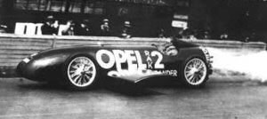
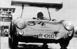
Although the foundations of aerodynamics were formulated over the past 200 years, not all its principles were immediately utilized by racecar designers. Naturally, the desire for low drag was recognized first, and early designers focused on streamlining their race cars. Although there was some experimentation with the addition of wings to influence the vertical load on the car during the late 1920s, this major innovation was completely ignored for the following 35 years. In 1928, Opel's experimental rocket-powered cars, the RAK 1 and RAK 2, were equipped with inverted wings on either side between the wheels to counteract high-speed lift. In 1956 a Swiss engineer and amateur racing driver called Michael May experimented with an inverted wing mounted over the cockpit of his Porsche 550 Spyder. Michael and his brother Pierre had recalled the use of such wings upon the Opel RAK. When May's car proved faster than the works Porsches, Porsche lobbied successfully for the appendage to be banned, under the pretext that it obscured the vision of following drivers, and May failed to pursue the idea any further.
 |
 |
Opel's RAK 2, with enlarged side-wings |
Michael May's 1956 Porsche 550 Spyder, with inverted wing |
Perhaps the most influential innovator in the field of racing car aerodynamics was Texan oil magnate, engineer and driver Jim Hall. Hall's Chaparral company linked up with the Chevrolet R&D department, headed by Frank Winchell, and competed in US sportscar championships such as Can-Am in the 1960s. In 1961, the Chaparral 1 sports car experienced lift at high speed, and Bill Mitchell, chief stylist of General Motors in the 1950s and 1960s, suggested using an inverted wing. In 1963 protruding front-mounted wings were fitted to prevent the front wheels of the Chaparral 2 from lifting off the ground. In 1965, the Chaparral 2C was fitted with a rear wing mounted on pivots, with a driver-adjustable angle of attack, and in 1966 the concept was extended to a dramatically high wing on the Chaparral 2E.
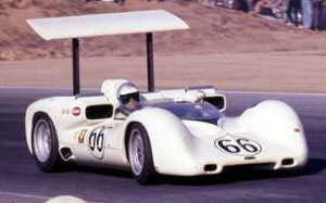 |
The high-winged Chaparral 2E of 1966 |
In 1966 the McLaren F1 team tested wings with great success, but due to
lack of resources, the team never found the time to revisit the idea, as recounted
by chief designer Robin Herd: "We didn't want anyone else to copy it, so we took the wings off, quietly put them in the back of the truck and continued with our normal testing. We decided we would look into it further, in private, when we had the time. But an F1 team in those days was so madly understaffed that we never got round to looking at it properly."
The logic was so simple. Wings generate this newly discovered thing called downforce. So stick them all over your car; big as you like.Big front and rear wings wobbling on what appeared to be flattened bars nicked from railings outside the factory. Not only was this means of support extremely tenuous, the effect on the rest of the car was pure guesswork. The wing supports were, in many cases, attached directly on top of suspension uprights because that's where the downwards load was needed in order to force the wheels onto the track. Straightforward logic.
In November 1967, Jim Clark raced an American Indycar called a Vollstedt, which possesed small wings, and during the Tasman winter series Clark recounted the grip and stability produced by this car to one of his Lotus mechanics. The mechanic extemporized a make-do wing from a helicopter rotor, which was fitted to Clark's car, and swiftly removed, but not before a Ferrari engineer had taken photographs of it. At the 1968 Belgian Grand Prix, Ferrari appeared with full inverted rear wings, and Brabham did likewise on the day after Ferrari's wings first appeared.
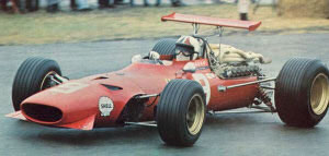 |
The winged Ferrari 312 of 1968 Belgian Grand Prix |
Ferrari's chief engineer Mauro Forghieri, his memory perhaps triggered by that Tasman photo taken by one of his staff of that experimental Lotus wing, had recalled that (before mentioned) Michael May - the engineer with whom he had worked perfecting Ferrari's fuel injection system a few years earlier - had once made a wing for his sports car. 'Michael was a friend as well as a consultant,' says Forghieri. 'He told me about the improvement in handling of his winged Porsche. The Chaparral convinced us even more about the idea',". Given that May's idea was, in turn, inspired by the Opel RAK, the introduction of downforce to Formula 1 in 1968 can be traced back to Opel's experimental rocket car of 1928!
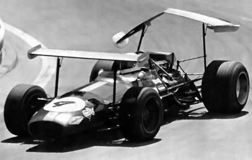
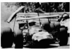 1969 at Spanish Grand Prix at Monjuich Park in Barcelona (picture up and left), strutted wing failures lead to a hasty application of new low, chassis mounted wing restrictions. Graham Hill and Jochen Rindt were extremely fortunate not to suffer grievous injury when supports to rear aerofoils which were the widest and tallest yet seen, collapsed just at the point where the Lotus 49B induced negative loading by becoming airborne over a very fast crest.
There was other potentially lethal moment. During practice for the 1968 French Grand Prix on the awesome road circuit at Rouen, Jackie Oliver had a truly enormous shunt. The entire front and back ends were torn off his Lotus 49B and no one, least of all Oliver, knows how he managed to climb from the wreckage without a scratch. Colin Chapman did not have the faintest clue about what had happened to his car. But Chapman spotted that the gearbox bell-housing had broken. Oliver had been flat out when the Lotus simply left the road and smashed into a brick gatepost at 140 mph. The rear end, complete with wheels, transmission and high wing, had ended up some distance from the battered tub and dust-covered engine. In fact, the failure proved to have nothing to do with the gearbox. Oliver had momentarily lost downforce when closely following another car; a common phenomenon now but, in 1968, you never knew what to expect.
High-mounted wings were banned after that.
At 1973 rear wings were mounted far behind the rear axle to achieve increased downforce but because this practice start to go to extremes, FIA restricted Rear wing overhang to 100cm behind the rear axle. 1976 rear wing overhang reduced further from 100cm to 80cm and front wing overhang defined at 120cm. 1983 rear wing width was reduced from 110cm to 100cm and rear overhang reduced from 80cm to 60cm, however the height was increased to 100cm to improve rearward visibility. That's a bit of history.
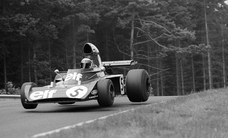 |
Jackie Stewart won three times at the Nurburgring. Flight like this, with all downforce Formula 1 have, today is not possible |
Improved performance are basically a result of increasing the tire adhesion by simply pushing the tires more toward the ground adding the grip. You can push tires to the ground in two possible ways: greater weight of the car, or aerodynamically, creating downforce. First way with added weight is not highly practical from obvious reasons.
Because of this additional load, larger friction (traction) levels can be achieved, and the vehicle can turn, accelerate, and brake more quickly. Furthermore, by controlling the fore/aft downforce ratio, vehicle handling can be easily modified to meet the needs of a particular race track.
The foremost and simplest approach to generate downforce was of course to add inverted wings to existing race cars. But how to do that?
Airplane wing design matured by the middle of the twentieth century and it was only natural that racecar designers borrowed airplane wing profiles to use on their cars. This approach, however, was not entirely successful due to the inherent differences between these two wing applications. A racecar lifting surface design is different from a typical airplane wing design for few reasons.
First, racecar front wings always operate very close to the ground, resulting in a significant increase in downforce. This increase is a manifestation of a phenomenon known as the wing-in-ground effect, which, interestingly, is favorable for the performance of both ordinary airfoils creating lift and inverted airfoils creating downforce. Of course, the effect does not come freely because a similar increase in drag is measured. Since many race cars use front wings mounted close to the ground, this principle is widely utilized in racecar design and wings should be optimized for this use.
Second,
in most forms of motor racing a large rear wing is used. In the case of open-wheel race cars these wings have very small aspect ratio (span/chord ratio), contrary to the much higher aspect ratio of airplane wings. The first result of the smaller aspect ratio was a significantly higher drag, but with the fringe benefit of delaying wing stall. This penalty could be reduced by adding very large end plates, seen on most race cars, which indeed improve the lift-to-drag ratio.
A second problem resulted from basing early designs on existing high-lift airfoil shapes, borrowed from airplanes having several elements (flaps and slots). But as noted, these airfoils were developed for airplanes having very wide wings (high aspect ratio), and therefore their performance was not optimized for racecar use. Recently, quite different, custom-designed airfoil shapes have been used to address this problem.
And the third major difference between aircraft and race-car wings is the strong interaction between the lifting surface and the other body components. Combined downforce increases as the wing approaches the vehicle's rear end. At a very close proximity the flow separates between the rear end of the car and the wing and the
downforce is reduced. The horizontal positioning (such as fore-aft) of the wing also has a strong effect on the vehicle's aerodynamics. Usually downforce increases as the wing is shifted backward. But racing technical regulations try to limit positioning of the wing. The very large change in the downforce of Formula 1, Indycar or prototype car is due to the increased underbody diffuser flow, due to interaction of two.
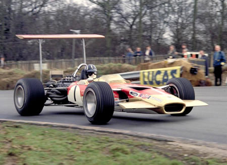
Lotus-49b wings
Early designs linked wings directly to the suspension, but several accidents led to rules stating that wings must be fixed rigidly to the chassis. No movement is aloud. The cars' aerodynamics is designed to provide maximum downforce with a minimum of drag; every part of the bodywork is designed with this aim in mind.
Like most open wheeler cars, Formula 1 feature large front and rear aerofoils, but they are far more developed than American open wheel racers, which depend more on suspension tuning and mechanical grip; for instance, the nose is raised above the centre of the front aerofoil, allowing its entire width of the wing to provide downforce. This component is the first to influence the air flow and if this is badly managed, the rest of the car will suffer.
The front and rear wings are highly sculpted and extremely fine 'tuned', along with the rest of the body witch have other aero appendages such as the turning vanes beneath the nose, bargeboards, sidepods, underbody, and the rear diffuser. They also feature aerodynamic appendages and flip-ups that direct the airflow toward desired area and try to keep airflow clean without disturbances. Such an extreme level of aerodynamic development means that an F1 car produces much more downforce than any other open-wheel formula; for example the Indycars produce downforce equal to their weight at 190 km/h, while an F1 car achieves the same downforce/weight ratio of 1:1 at 125 km/h to 130 km/h, and at 190 km/h the ratio is roughly 2:1. Theoretically, F1 cars can drive upside down from 130 km/h.
Size, number of aerofoils and position of the wings is regulated by FIA rules. Because of this limitations, wings require use at high angles of attack to create sufficient downforce. This lead to high aerodynamic drag coefficient, from 0,7 to 1 Cx compare to modern road car which has a Cx value between 0.25-0.30.
The aerodynamics are adjusted for each track; with a relatively low drag configuration for tracks where high speed is relatively more important like Autodromo Nazionale Monza, and a high traction configuration for tracks where cornering is more important, like the Circuit de Monaco.
During the Formula 1 history there was a lot of controversy surrounding the wings designe and wings flexibility. Any kind of bodywork flexibility is not allowed. Moveable aerodynamics had been made illegal in 1969. There was an air of controversy around the 1972 the Lotus 72D and its rather suspect rear wing. 72D was fitted with a rubber bush on the rear wing's mount to allow it to change its angle at high speed. In the pits a mechanic or scrutineer was able to put all his weight on it without the wing moving, but under the high aerodynamic loads on a long straight the angle of the whole wing changed and reduced drag. The wing avoided detection until McLaren's Denny Hulme spotted Fittipaldi's helmet appearing above the wing on long straights. At the risk of being rumbled, Lotus removed the rubber bush and no further action was taken.
Fresh example of illegal flexible bodywork (read: wings) was Red Bull Racing flexi front wing controversy. Detailed article about that you can read here.
Front Wing
If you say that aerodynamics itself determines 90 per cent of a car's performance, then the front wing is 60 or 70 per cent of the 90, and that's because it's the part that hits the air first and dictates how it flows over the rest of the car, hence the vortices it generates are particularly important.
 On the modern F1 car, only relatively small part of the wing is used to create downforce. Rest of the wing is used for creation of vortices and conditioning the air streams to be used downstream, to shape the streams around front wheels, toward sidepod openings and to seal the floor.
Downstream vortices are generated by lateral pressure gradients within the front wing assembly, and these exist across the endplate, at the transition between the wing-section and the neutral inner-section dictated by regulation, at the inner tips of the front-wing flaps, and at the arched sections of the front wing. Aerodynamically speaking, a Formula 1 car is an interconnected system of vortices. When a vortex separates from a solid surface, he possess a low pressure core, in some sort of balance with the centrifugal 'force' of the air spiralling around the vortex on helical trajectories. Oriented in a streamwise direction, such vortices can be particularly useful, both for the direct generation of downforce, and to act as air curtains, sealing off other low pressure areas, for example undertray area.
If your front wing creates a turbulent wake or has a poor vortex generation, then every component you develop downstream of the front wing must be optimized to work in that environment, often with less success.
However, if the wake is good, then the downstream aerodynamic surfaces can be made to work harder and the complete package will than create more overall downforce. The front and rear wings produce the majority of the overall downforce, approximately 66%, on an F1 car. The key to creating overall car downforce is to manage the way air separates around the front wing. The relationship between the front wing and the track is a delicate one; with the wing generally being more efficient the closer it is to the track. Therefore, the front wing is low to the ground to obtain as much advantage from ground effect as possible, and generally, before rules change 2008, has one full spanning flap. After 2008, flap elements are closer to the outer sides of the wing. Developments usually concentrate on the profile of the wing, endplates and the use of flaps.
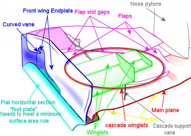
The front wings on the car can produce 25-40% of the cars downforce. Each front wing is made of mainplane running almost the whole width of the car suspended from the nose. Onto this are fitted two aerofoil flaps, one on each side, which are the adjustable parts of the wing. These flaps are usually made of one piece of carbon fiber, but Ferrari has used two small flaps rather than one large one. On each end of the mainplane there are endplates.
The wing flaps on either side of the nose cone are asymmetrical. They reduces in height nearer to the nose cone as this allows air to flow into the sidepod radiators and to the underfloor. If the wing flap maintained it's height right to the nose cone, the radiators would receive less airflow and therefore the engine temperature would rise. The asymmetrical shape also allows a better airflow to the underfloor and the diffuser, increasing downforce. The wing mainplane is often raised in the center. This again allows a slightly better airflow to the underfloor aerodynamics, but it also reduces the wings ride height sensitivity.
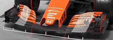
This comes from flow visualizations on the wing, which shows its suction power is so strong that it pulls air in from angles not straight with the centerline of the car.
Ferrari come to conclusion that the air which is approaching a normal, straight leading edge wing at an angle, do not make wing working to its full potential. By shaping the leading edge by the correct angle, maximum efficiency is obtained. Until 2008, when rules changed, all teams make use of this (see picture below).
Of course, different track demand different front wing design. Take for example Monza front wing. Monza spec front wing only needs to produce enough downforce to balance the low drag rear wing, thus the it's size is dictated by the car's rear aero. Monza is extremely low downforce track and teams normally uses simplified wing design by removing the winglet cascade elements, but they often retains the vertical fin like elements. The wing also uses a single piece flap or few flaps of reduced size. The wings downforce is mainly reduced by the smaller element flap(s), but this also help to reduce negative effect of turbulence from other cars. As much as the front wing is a downforce producing device, fins and flaps, in case of Monza, are all about vortex generation to influence the turbulence produced by the front tire.
Very important vortices are produced by fins. These will trail spiralling vortices over the upper edges of the front tire, which will reduce airflow separation that the wheel forms over the top of the tire tread, but also in controlling the vortices formed by the rotating tire and the separation of the airflow behind the tire. These counteract the unwanted turbulence created by the tire, which greatly improves airflow back along the car, to prevent the tire's vortices being sucked inside the low pressure area formed by the coke bottle bodywork.
End plates
Ever wondered why F1 designers go to such extraordinary lengths to refine the design of the front wings and particularly the endplates? Top teams bring something new in this area to almost every race.
Why is like that and why that is so important, check in this article.
Rear Wing
 The rear wing is a crucial component for the performance of a Formula One racecar. These devices contribute to approximately a third of the car's total down force, while only weighing about 10 kg.
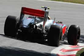
Pictures shows a Williams (before 2009) and McLaren (after 2009) rear wing. Usually the rear wing is comprised of two sets of aerofoils connected to each other by the wing endplates. The upper aerofoil, consisting of one element, provides the most downforce, and varied from race to race. The lower aerofoil, consisting of one element, it is smaller and provides some downforce. However, the lower aerofoil creates a low-pressure region just below the wing to help diffuser create more downforce below the car. The rear wing, same as front wing, is varied from track to track because of the trade off between downforce and drag. More wing angle increases the downforce and produces more drag, thus reducing the cars top speed. So when racing on tracks with long straights and few turns, like Monza, it is better to adjust the wings to have small angles. Opposite to that, when racing on tracks with many turns and few straights, like Austria, it is better to adjust the wings to have large angles.
 Splitting the aerofoil into separate elements as seen in this picture is one way to overcome the flow separation caused by adverse pressure gradients. Multiple wings and flaps are used to gain more downforce in the rear wing. Two wings will produce more downforce than one wing, but not twice as much. Today rules allow use of only 2 wing elements. The lift coefficient increases and lift/drag ratio decreases when increasing the number of aerofoils. The position of the wings relative to each other is important. If they are too close together, the resultant forces will be in opposite directions and thus cancel each other.
Rear wing endplates are designed with form and function in mind. Because of their form they provide a convenient and sturdy way of mounting wings. The
aerodynamic function of these endplates is to prevent air spillage around the wing tips and thus they delay the development of strongly concentrated trailing vortices.
Trailing vortex or induced drag is the dominating drag on any kind of wings. An additional function of the rear endplates is to help reduce the influence of upflow from the wheels.
Flip-Ups
 Lift due to exposed wheels is a major problem for F1 racecars since regulations prohibit enclosing the wheels within the bodywork. Exposed wheels generate upward lift forces that decrease the downforce created by the wings and other structures. This positive lift may reduce downforce by approximately 11% on a typical F1 track. Plus, they disturb the air flow around rear wing.
To resolve this problem, engineers design flip-ups on the rear section of the sidepods, in front of the rear tires. Flip-ups as seen in picture guide air over the rear wheels while creating some downforce and shielding rear wing from influence of dirty air coming from front and rear wheels. Flip-ups are not allowed any more after rules changes for year 2009 and after.
Venturi Channels
Simple fluid dynamics says that flow that accelerates looses pressure. This is in fact the nozzle effect (or Venturi effect), when flow in a convergent nozzle accelerates and looses pressure. Pressure is then recovered in the diffuser.
By shaping the underbody as an inverted wing, or with appropriate channels, or even with a simple scant angle that work with the Venturi effect, the overall pressure between the underbody and the ground decreases creating additional downforce. To know more about this check out article "Bernoulli Equation".
Though Bernoulli's principle is a major source of lift or downforce in an aircraft or racing car wing, Coanda effect plays an even larger role in producing lift. To know more about interaction of Bernoulli principle and Coanda effect check my article here.
Body work
The need for generating high values of downforce makes engineering go around the regulations. This sometimes produces details called body work, which are not simply cosmetic changes, but can make a difference of a few tens of a percent.
On the begening of the season factories are 100% operational to ensure that the cars leave the factpry with enough spares for the first race. For example team wants 6 front wings at each race, with 4 being considered the bare minimum. Typically a team may go with 2 to 3 wings of last specification and 2 to 3 updated wings. Each front wing can take up to 4 to 6 weeks to make from scratch so if any were damaged on the track, production will struggle to replace it in time. From an operational and data analysis perspective this last few weeks before first race will probably be the busiest few weeks of the year.
The regulation changes for 2009 are some of the most extensive ever introduced to Formula One racing and fall into three main areas - aerodynamics, KERS and tires. Formulated with help from the Overtaking Working Group's (OWG) engineers, the new rules aim to (1) reduce the aerodynamic sensitivity of the cars to turbulence; (2) increase overtaking opportunities; and (3) slow the cars in the very quick corners. To compensate for the loss of downforce from the aerodynamic changes, slick tires have been brought back for the first time since 1997 to boost mechanical grip. As a result of the changes the 2009 cars appear quite different to their predecessors, with the removal of the vast majority of bargeboards (now only allowed in a very small area), winglets, chimneys, flip-ups and cooling gills leading to much cleaner looking designs.
As part of the aero changes designed to allow cars to be able to follow each other more closely (and hence promote overtaking), the 2009 front wing is both lower (75mm instead of 150mm) and wider (1800mm instead of 1400mm). The wing also features a universal central section (500mm), which all teams' designs must comply with this season, and a flap section that can be adjusted by the driver twice a lap over a range of six degrees.
The rear wing becomes taller (up 150mm to bring it level with the top of the engine cover) and narrower (750mm from 1000mm).
As a part of 2014 rules change, the width of the front wing will be reduced by 15cm, from 180 cm to 165 cm. This will change the alignment of the wing endplates relative to the front tires. Previously the wing's 180cm width was the same as the car's total width, so it was relatively easy to design front wing endplates to minimise the drag produced by the tires and adjust vortices in best way. Next year, to compensate for the narower wing, the endplates will be even more curved on the outside so that they can still sand strong airflow to the outside of the tires to keep efective outwash.
For 2019 there was some minor rules change which involve wings.
Front wing is now wider, higher – and much simplified. The wing's width is increased by 200mm, its height by 20mm, and it's moved forward by 25mm. Complex endplates that outwash airflow around the front tires are banned. Instead, much simpler endplates mean almost the full width of the wing is devoted to direct downforce generation. The multiple under-wing strakes seen on 2018 cars are now limited to two each side. All this is done to make following car less sensitive to aerodynamic disturbance and so creates a less choppy 'wake' for a following driver to deal with.
Rear wing is now higher, wider, simpler to help promote even closer racing.
Height is rised by 20mm, taking the wake coming off the back of the car higher into the air. Combined with a width increase of 100mm, the larger wing assembly creates a bigger hole in the air – to the benefit of cars trying to slipstream behind. Also, limitation has been placed upon the pressure-equalising endplate slots of 2018.
DRS opening is increased by 20mm, boosting its potential power by around 25 percent.
Also, to increase visibility of cars in poor weather conditions, and hence improve safety, as well as the traditional rear central light, two additional rear LED lights, fitted verticaly one on each endplate. These must be illuminated at all times when a driver is using intermediate or wet-weather tires.
Back to the top of the page