Gearbox
To know more about "shifter", and to get complete picture, first check my article about gear ratios and transmission.
The classic answer to "What is the Gearbox for?" is "To keep the oil in", which is fair enough unless you want to know something more!
Some call it gearbox and some transmission, depends on which side of the Atlantic you're on. To the Europeans, it's a gearbox. In British English the term transmission refers to the whole drive train, including gearbox, clutch, differential and final drive shafts. In American English, however, the distinction is made that a gearbox is any device which converts speed and torque, whereas a transmission is a type of gearbox that can be "shifted" to dynamically change the speed/torque ratio, such as in a vehicle. But we can say that a gearbox is the central component of a transmission system.
And now when you read gears article and understand how simple gearbox work, let's talk about more complex stuff!
The two primary functions of any gear case are to rigidly mount the bearings of any gear shafts, such that the gears maintain accurate meshing under the parting loads induced as they transmit torque, to keep dirt out, and to keep lubricating oil in. Additionally, the case must locate selector mechanisms and oil pumps, and have access panels to permit assembly. As designed into almost any modern racing car, the case also forms part of the primary chassis structure, mounting the rear suspension and feeding the suspension loads to the rear face of the engine. Spare space within the gear case may be used to accommodate oil for the engine, the gearbox if it is dry-sumped, the hydraulics, and the mandatory catch tank. Finally in recent years, the gearboxes used in the leading Formulae must mount a rear impact absorbing structure, normally integrated into the detachable rear cover for the final drive/differential, which also mounts the rear wing structure.
 |
Animation of sequential gearbox |
"Simple" gearbox, as explained on the begining of Gears article, is not in use in racing any more. Only most basic racing categories are using it. In Formula 1 this kind of gearbox is not in use more than 20 years. Sequential gearbox is stuff of the day in our sport, take rally, DTM, Formula 1, almost all open wheel classes, WTCC, Indy, truck racing... Sequential transmissions usually use the rotation of a drum to switch gears.
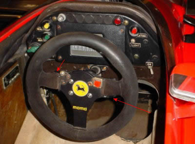
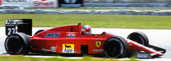 Ferrari 640 with Mansel driving
Ferrari 640 was the first F1 car using a semiautomatic sequential gearbox 1989 in the Brasilian GP. Car was driven by Nigel Mensel.
Ferrari had been working at a sequential semi-auto (or manual-hydroelectric activated gearbox) for many years, and had several iterations that were built and ran. It was primarily due to drivers’ opposition that they decided to shelf the project.
 1988, John Bernard, in this time Ferrari technical director, completed something that had been in the works for many years, and this innovation was accepted and adopted for first time in 1989. Idea was to speed up gear change to maximum, and get rid of clutch pedal. First idea in time of development was to have one lever on right hand side of the driver, on the place of "old" "H" gear shift lever. Driver will move this lever only backward and forward to go trough gears (sound familiar?). During development period Bernard got better idea. He put two buttons on each side of the steering wheel to prevent driver to move hands from the steering wheel.
Later, they change this idea to two paddles behind a wheel. They added third, clutch paddle little bit offset and smaller then first two. Left side paddle was used for downshift, and right paddle for upshift. Clutch paddle was smaller because this one is in use only during the start, stop and in some emergency situations. During normal race clutch was operated automatically, together with gear change forks with help of electronically controlled electrohydraulic system.
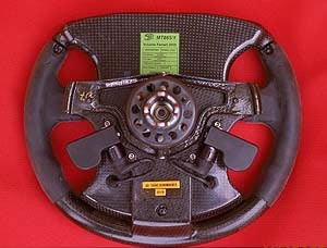 |
Paddles behind a wheel |
 |
Ferrari 640 steering wheel with innovative paddles behind the wheel |
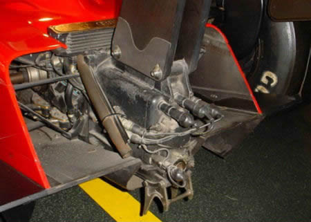 |
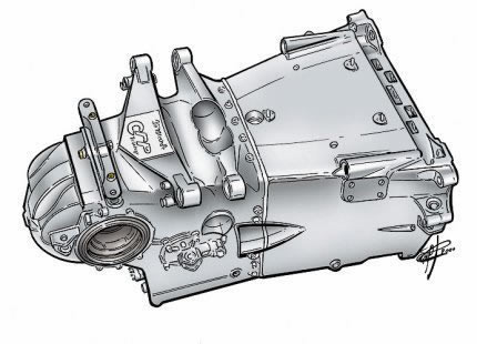
Ferrari 640 innovative sequential gearbox. Note that diffuser is very crude and simple. |
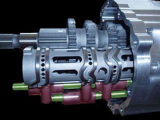 |
Selector drum of an modern sequential gearbox |
 |
Honda RA106 Formula 1 Gear Selector Barrel |
For many years it was the convention on F1 cars to locate the gear clusters behind the
differential, for ease of access in order to change gear ratios, although this compromised weight distribution and aerodynamic performance. The current trend, with the gear clusters at the front (engine) end of the gearbox, means that the gearbox must be removed to change the gear ratios. The gear cluster (input shaft and output shaft) is mounted in a removable cassette, which can be removed once the gearbox/rear suspension/wing assembly has been removed from the rear of the car. The input shaft and output shaft each carry seven gears, and each pair of gears (one on the input shaft and one on the output shaft) is carefully selected to give the required gear ratio.
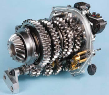 |
Inside Formula 1 gearbox, the gear clusters are mounted in a removable cassette. Much easier to work with. |
The FIA from 2011 regulations stipulate that each car is allowed 30 pairs of gear ratios from which to choose during the entire season, and these 30 ratios must be declared to the FIA before the first race of the season. The 2010 FIA regulations stipulated that all gears must be manufactured from steel, with a minimum weight (0.6kg) for gear pairs, and a minimum thickness (12mm) for each gear. All cars must be fitted with a reverse gear to comply with the FIA regulations, and reverse is operated using a button on the steering wheel which engages an intermediate gear between the gearbox input and output shafts to reverse the direction of rotation of the output shaft.
Before 2014, FIA technical rules allow gearbox's with 4 to 7 forward speed and one reverse gear. After big rule revision for 2014 an beyond, gearbox has to have 8 forward and reverse gear. Reverse gear is mandated. The driver initiates gear changes using paddles, and electro-hydraulics perform the actual change as well as throttle and clutch control. The current, after 2014, heavily hybridized Formula 1 power unit have a much more flexible torque delivery then previous V8 engines and they are therefore much less reliant on having multiple gear ratios to keep them within narrow power band. And it seems strange that after 2014 F1 is using more ratios with the more flexible engine. But the real difference is that now, after 2014 rule change, after teams selected the ratios, they have to remain the same all year. This means that same ratios will be used in Monaco or in the Monza. The multiple gear ratios also help with fuel economy. The idea to fix the gear ratios for the season was to make cost saving.
Since the Ferrari 640 F1 showed the performance benefits of semi-automatic gearboxes back in 1989, all F1 teams adopted that idea. Development has been astonishing: they've become smaller, lighter (because of the use of advanced materials, particularly in the gears and casing). And, most importantly, they become faster. Talking about "old" F1 sequential gearbox (two or three years ago), they become so fast that "normal" person can't understand and can't believe if that is possible. Complete gear change happened in 10-15 millisecond.
In this time:
- Driver gives a command to up or downshift.
- Electronic control system check position of the clutch, engine speed and wheel speed (using different sensors in engine and differential)
- Initiating clutch opening (electronics give a signal to electrohydraulic system to operate solenoid valve, valve open and release high pressure oil into hydraulic piston, piston push clutch discs to open position)
- Changing the gear. Disengaging old one and then engaging new, selected gear. (electronic give a signal to electrohydraulic system to operate solenoid valves to operate gear selector forks and to adjust proper gear to desired position)
- ECU is checking new proper position of gears, and comparing this data with engine and wheels speed in this instant (using different sensors in motor and differential. If driver select wrong speed, gear change will not be done)
- Closing the clutch if item 5 is OK (electronic give a signal to electrohydraulic system to close solenoid valve and to release hydraulic oil from piston and to close the clutch)
- If item 5 is not OK, electronic control system will try to engage proper gear, or to return to originally engaged gear.
All this checking is necessary because of high speed of the system. If anything goes wrong during gear change process, anything, we can see white smoke behind car or blocked rear wheels and spin.
2008 Honda Formula 1 Gear Selector Hub
But only in the last few years we can see some very serious, inventive thinking been applied to developing a step change in the way gearboxes work. This 10-15 milliseconds explained before, for them is to much of lost time. They want something better and faster. F1 engineer are never satisfied (that's why they are F1 engineers), and they started to think about seamless gearshift.
With the single barrel sequential shifter was able to make extremely fast shifts, the shift was still an interruption in power delivery and hence reduced acceleration of the car. With seamless gearshift now used, shift can be done with no measurable interruption to power transmission. This alone is worth around 0.3 seconds per lap.
The system relies on two shifting barrels, not one as before. One operates first, third, fifth and seventh gear, and the other
second, fourth, sixth and eight gear. To achieve a seamless gearchange we essentially engage two gears at once by moving separate barrels and rely on the fact that it takes a finite time, just a few milliseconds, before both gears would actually engage and lock the gearbox with disastrous results. In this very short period we have to disengage the previous drive gear to ensure such catastrophe. It sound complex, and indeed, it is.
Despite the systems having been in use for several years, there is still little information coming from the teams on how they work. What is known is that the systems retain the conventional two-shaft gearbox and single clutch. A double clutch would provide a seamless shift, but this is banned under the current rules. No F1 engineer wants to talk about that. Every team has his own way to do the job.
 |
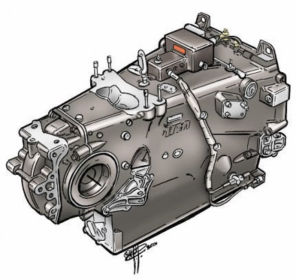
Red Bull Racing RB6 gearbox casing, gear clusters, controls and differential. The layout of the gear clusters is conventional, with two shafts – an input shaft and output shaft – located longitudinally inside the gearbox casing. The clutch is attached to the end of the input shaft, at the front of the gearbox. A bevel gear (pinion) on the rear end of the output shaft takes drive to the differential, via an intermediate bevel and a reduction gear on the cross-shaft. All the gears are straight-cut to minimise power losses and to provide the maximum possible strength and durability; the gears of most road car gearboxes are helical, to reduce noise. |
While almost all teams have seamless boxes, the choice of gear case material varies, with the choice being between aluminum, magnesium, titanium or carbon fiber, along with the additional choice of hybrids of the metals bonded with carbon fiber. Gear case stiffness and weight are very important. Back part of rear suspension wishbones and dampers are connected to the 'box and stiffness is a paramount. Also, back crash structure is fitted on gearbox. 'Box is located behind engine on relatively high position and behind rear wheels axel, and that is the reason why weight is also very important.
In 2007, only Honda and McLaren ran full carbon fiber cases, and Ferrari evolved their titanium skeleton with bonded carbon skins. All of the other teams ran a metallic (Magnesium, Titanium) gearbox, albeit with some level of carbon fiber bonded to specific areas for stiffness.
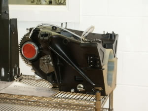
Magnesium gearbox
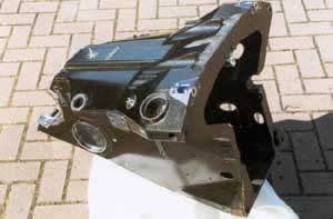
Titanium gearbox
Hybrid technology gearbox
Carbon fiber gearbox designed 1998 by John Barnard for Arrows
All materials have his pros and cons. Carbon fiber is very light but torsional stiffness can be a problem. Aluminum has a torsional stiffness, but weight and durability is a problem. Titanium is stiff, light and durable, but extremely expensive material and hard to work with. Anyway, carbon fiber is lighter then titanium.
Ferrari use titanium skeleton with bonded carbon panels. In this way, they are using positive sides of both materials. Light and extremely stiff. Bay the way, this type of 'box casing was again invented by John Bernard and for first time used by Ferrari F1 team. I think it was 1988.
Shape of gearbox is extremely important because they are a part of back side aerodynamic package, and part of diffuser. In 2005, the gearboxes had to become smaller because there was less space available due to the new aerodynamics regulations. The change from V10 to V8 engines has allowed the teams to extend box little bit.
Formula 1 engineers don't allow themselves to get excited about gearboxes. They instruct the design office to package it to a certain size, to optimize the aerodynamics around the back end - then, provided it doesn't break every second race (Red Bull in 2007), job is not done.
People who've got it right don't have much time to congratulate themselves: 2008 technical regs call for 4 race gearbox, and new electronics provided by McLaren/Microsoft.
After that, 2009 technical regulations confirm use of kinetic engine recovery systems, and expect gearboxes to last even more races. Technical regulations for 2011 say that gearboxes will have to last five races instead of four previously. Gearbox technology is going to have to move on yet again.
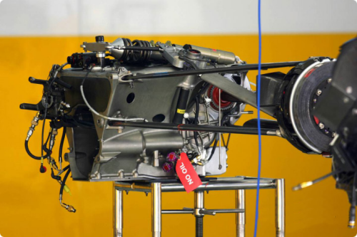
Formula 1 Gearbox from 2009 season with rear crash structure. You can see rear suspension elements attached to gearbox, and on the top you can see rockers, dampers, pushrod element and torsion bar.
A gearbox is a carefully cultured, very secret high-tech product, and its 400 individual parts are all specially produced for each team- right down to the bearings and seals. Naturally, that all has its price: a Formula 1 gearbox, according to expert estimates, costs about 150,000 euros.
Until 2009 reliability of the individual parts varies: while the gear wheels were replaced after every race, the gearbox housing normally lasts for the whole season or close to that.
Many of the internals come from outside suppliers such as Xtrac and Hewland.
Founded by Mike Hewland in 1957, Hewland Engineering invented the bespoke racing car gearbox and it has supplied the worlds racing car constructors ever since.
Today, Hewland supplies 21st century motorsport transmissions to an amazing client list, spanning a worldwide and diverse array of racing series.
F1 gearbox used by Ferrari during season 2000
A little bit of history
Gearbox design by John Barnard
CFRP is an excellent material for tanks, covers, and impact structures, but is not so good at accepting point loads. Joints, bearing housings and suspension mountings all need very careful detail design to spread the concentrated loads into the material and, as he has demonstrated many times over his years at Chaparral, McLaren, Ferrari, Benetton and Arrows, John revels in and excels at detail design.
John has never been particularly happy with cast magnesium, and had already got rid of it for uprights back in 1975, on the Parnelli Formula 1 car. When he joined Ferrari for the second time in 1993, they were using a magnesium case, longitudinal gearbox, with the gears behind the final drive, and employing the paddle shifting system that John had pioneered during his previous tenure there. The casting technology at that time produced magnesium with the possibility of porosity and variable wall thickness, due to problems of positioning the cores accurately during the casting process. Designers had to increase the structurally optimum wall thickness to allow for these deficiencies and, along with magnesium's well-known reduction in stiffness above about 100°C, this resulted in a combined bell-housing/engine oil tank/gearbox case weight of around 27.5Kg. The loads put through the gear case as part of the chassis of the car, and the flexing of the hot case often generated fatigue-cracking around stress raisers in a new design, and even cases to a proven design needed replacing after half a season at the most.
John wanted to do something different for the 1994 car. "I looked at a transverse layout, to see if I could line up the bearings of the gear shafts and final drive/differential into planes and move the weight ahead of the rear wheels. In that way I could hang them on flat plates and hence fabricate the gear case. I wanted to do it in CFRP, but had no confidence to hang the bearings in that material. Instead we used steel." The gear case was made up as a fabricated steel box, with the sides machined out of 25mm plate, CNC-milled down to 1.2mm wall thickness and ribs. The gear case weighed only a little less than the magnesium one it replaced, which was a disappointment. "In mid-season we switched to titanium instead of steel, and gained an immediate 40% weight reduction." Manufactured at Barnard's Ferrari Design and Development base in the UK (now B3 Technologies), they had to get to grips with welding titanium in inert gas tanks. "There were few problems: to avoid distortion during welding thin sections, it had to be done in the right order and allowed to cool between steps." Machining the titanium plates required considerable investment in CNC machine tools, but otherwise John claims this approach is not more expensive than traditional techniques. Process time is longer however, and cannot compete with casting rates.
The weight reduction at the rear of the car was most valuable, but the increased hot stiffness also meant better gear reliability. As the gears do not displace significantly under load, they can be ground to truer profiles for greater efficiency and durability.
The '94 transverse gearbox was the first to use John's internal-spline dog-ring arrangement. The three face dogs on each gear engaged with internal dogs, which themselves had splines on their inner diameter to engage with the shaft. The width saving was around 6mm per dog-ring, to give an overall width reduction of 18mm. He has used this arrangement ever since. For 1995, the fabricated titanium gear case bolted to a CFRP bell-housing/oil tank, onto which the suspension units were mounted and into which the majority of the suspension loads were fed. There were some initial problems with cracking and oil leaks at the suspension mounting points on the CFRP oil tank. These were caused by insufficient overlaps at the joints, and after the tank was lined with a tank slushing compound no further leaks occurred. The '94 and '95 gearboxes were a 3-bearing arrangement, but in 1996 John went to a 2-bearing design. This year was also the first in which a CFRP rear impact crash structure was fitted, albeit one year ahead of the FIA requirement. The same basic arrangement - CFPR bell-housing/titanium fabricated gear case/CFRP rear case and impact structure - has been in use at Ferrari ever since, but in longitudinal layout since 1998.
With 4 years of successful experience of the CFRP/titanium gearbox construction under his belt, John decided to take the next step when he joined Arrows to design their 1998 car. He was not the only Technical Director to believe the time was right for a full CFRP gearbox case: Alan Jenkins committed the fledgling Stewart team to one too. Both boxes were longitudinal, and both had bonded in transverse bulkheads to carry the gear-shafts' bearings. However, where the Arrow's case employed titanium for the bulkheads, the Stewart used aluminum, and the different success of the two designs is rooted in this variation. While Arrows continue to use Barnard's basic arrangement, Stewart, now Jaguar, have reverted to magnesium after a lot of trouble with the joints between the aluminum bulkheads and the CFRP casing, in spite of eventually solving the problems. John: "The bonded joints are the key to building a successful gear case in CFRP. The joints must have fully machined mating faces and the correct surface preparation. We experienced no leakage problems with the joints (the bulkheads keep the oil in), and I suspect it was Stewart's choice of aluminum, which has over twice the thermal expansion of titanium, that caused them problems. The coefficient of thermal expansion of CFRP is very low, and when the box heats up to its running temperature of over 100°C, quite a lot of stress can build up in the joint between the two materials."
Carbon fiber gearbox designed 1998 by John Barnard for Arrows
One problem occurred in initial testing of the gearboxes, which was so hard to diagnose that it nearly led to the abandonment of the CFRP design, even though it eventually transpired that the problem was unconnected to the use of the material. The gear-engagement dogs were chipping such that the gear-change deteriorated quickly and failure followed shortly after. The problem was eventually traced to .001" (40 micron) undersize gear hubs, on which the dog-rings moved. This caused the dog-rings to tilt slightly when located in the out-of-gear position, and allowed the dogs to touch the corresponding dogs on the gear, which then chipped. John: "It was a classic example of how novel features in a design tend to be blamed for any shortcomings, even though the cause may be rooted in conventional engineering processes."
The CFRP main case weighed under 9kg, and the rear case, including rear impact structure, weighed 4kg, the two assembled together totalling 14kg. This compared well with the equivalent magnesium cases that they replaced, which weighed 25kg. The saving at the rear of the car translated into more available ballast to be mounted forward, in an era when every effort was being made to move weight forward to make the wide front tires work. The all-CFRP design gets rid of the joint between the bell housing and the gear case, increasing overall stiffness. A surprising advantage was that the oil in the box ran cooler - 100°C instead of the more usual 130°C. Part of this is due to the greater efficiency of the correctly meshed gears, but John also believes that the insulating properties of the carbon fibre/Bismalamide resin casing prevented heat being transferred from the hot air stream from the radiators and around the exhaust pipes to the oil. Altogether the Arrows gear cases have been reliable, lasting more than a season.
Carbon fiber gearbox designed 1998 by John Barnard for Arrows
Among the myriad rule changes for the 2011 season, one of the less prominent was that gearboxes must now last for five consecutive events rather than four in 2010. Furthermore, each team had to choose 30 ratio options before the season began to cover the demands of the 19 circuits, which must be able to cope with the slowest corners at Monaco, and the long straights of Monza, with DRS enabled. This rule means that the teams have 30 ratio options available, not that only 30 ratios can be used.
For example,
Valencia Street Circuit requires the most gear changes per lap. Valencia Street Circuit requires 64 gear changes per lap; only Singapore requires more, with 71 changes per lap. This equates to over 3,648 changes per race, compared to a season average of 3100 gear changes. This means, on average, the drivers are changing gear once every 85 metres, compared to once every 61 metres in Monaco, or at the other extreme, once every 143 metres in Spa. Last year, a gearbox was used for between 2,100 and 2,500 kilometers; for 2011, this is expected to be between 2,600 and 3,000 kilometers. During the five-race cycle, a gearbox would therefore perform over 25,000 gear shifts.
The gearbox typically runs at up to 130 degrees Celsius and has to transmit around 5000Nm at the final drive. The gearbox itself weighs less than 40 kilograms and includes well over 500 individual components; these include not just gearbox functions, but also mounting points for the suspension, the rear crash structure and many hydraulic components.
Check out my Shifting Technique article
ARTICLE 9 : TRANSMISSION SYSTEM
9.1 Transmission types :
No transmission system may permit more than two wheels to be driven.
9.2 Clutch control :
The following applies only to the main drivetrain clutch or clutches, any clutch used exclusively as part of an ERS is exempt.
9.2.1 If multiple clutch operating devices are used, they must all have the same mechanical travel characteristics and be mapped identically.
9.2.2 Designs which allow specific points along the travel range of the clutch operating device to be identified by the driver or assist him to hold a position are not permitted.
9.2.3 The minimum and maximum travel positions of the clutch operating device must correspond to the clutch fully engaged normal rest position and fully disengaged (incapable of transmitting any useable torque) positions respectively.
9.2.4 Designs or systems which in addition to typical inherent hydraulic and mechanical properties are designed to, or have the effect of, adjusting or otherwise influencing the amount, or rate, of engagement being demanded by the FIA ECU, are not permitted.
9.2.5 The amount by which the clutch is engaged must be controlled solely and directly by the driver with the exception of : a) Stall prevention. b) Gearshifts. c) Bite point finder where brake pressure, wheel speed and driver clutch demand safeguards are used. d) De-clutch protections. e) Drivetrain protection on the track outside of any start lockout period or immediately following stall prevention activation only. f) Test signals enabled only when the car is connected to the garage system. The relationship between the clutch operating device in the cockpit and the amount of clutch engagement may be non-linear but must remain fixed.
9.2.6 When the clutch operating device is released from its maximum travel position it must return to its resting position within 50ms. The maximum delay allowed, computed from the respective positions as recorded by the ADR or ECU, between the clutch driver control input signal and the corresponding output demand being achieved is 50ms.
9.2.7 Any device or system which notifies the driver of the amount of clutch slip or engagement is not permitted.
9.3 Traction control :
No car may be equipped with a system or device which is capable of preventing the driven wheels from spinning under power or of compensating for excessive torque demand by the driver. Any device or system which notifies the driver of the onset of wheel spin is not permitted.
9.4 Clutch disengagement :
All cars must be fitted with a means of disengaging the clutch for a minimum of fifteen minutes in the event of the car coming to rest with the engine stopped. This system must be in working order throughout the Event even if the main hydraulic, pneumatic or electrical systems on the car have failed. This system must also disconnect any ERS system fitted to the car. In order that the driver or a marshal may activate the system in less than five seconds, the switch or button which operates it must :
a) Face upwards and be recessed into the top of the survival cell no more than 150mm from the car centre line.
b) Be designed in order that a marshal is unable to accidentally re-engage the clutch.
c) Be less than 150mm from the front of the cockpit opening.
d) Be marked with a letter "N" in red at least 40mm tall, with a line thickness of at least 4mm, inside a white circle of at least 50mm diameter with a red edge with a line thickness of at least 2mm.
9.5 Gearboxes :
9.5.1 A gearbox is defined as all the parts in the drive line which transfer torque from the power unit output shaft, as described in Article 5.3.2, to the drive shafts (the drive shafts being defined as those components which transfer drive torque from the sprung mass to the un-sprung mass). It includes all components whose primary purpose is for the transmission of power or mechanical selection of gears, bearings associated with these components and the casing in which they are housed.
9.5.2 In this context the following parts are not considered part of the gearbox and may be changed without incurring a penalty under the F1 Sporting Regulations. If changing any of these parts involves breaking an FIA applied seal this may be done but must be carried out under FIA supervision :
a) The clutch assembly and the power unit output shaft, provided this is located prior to any mechanical speed reduction from the engine.
b) The clutch actuator and clutch release bearing(s).
c) Inboard driveshaft joints and seals but not their housing if that housing is integral with the gearbox output shaft and therefore part of the sprung mass.
d) The hydraulic system prior to the point at which it produces direct mechanical movement of the gear selection mechanism by means of hydraulic actuator(s).
e) Oil, oil pumps, oil filters, oil seals, oil coolers and any associated hoses or pipes.
f) Electrical sensors, actuators, servo valves and wiring.
g) Any parts associated with the suspension or functioning of the sprung suspension that are attached to the gearbox casing.
h) The rear impact structure provided it can be separated from any gearbox casing.
i) Any other component mounted to the casing whose primary purpose is unconnected with the transmission of power or selection of gears.
9.6 Gear ratios :
9.6.1 The number of forward gear ratios must be 8.
9.6.2 Each competitor must nominate the forward gear ratios (calculated from engine crankshaft to drive shafts) to be employed within their gearbox. These nominations must be declared to the FIA technical delegate at or before the first Event of the Championship. For 2014 only a competitor may re-nominate these ratios once within the Championship season, in which case the original nomination becomes immediately void, except for the continued use of used gearboxes (according to Article 28.6 of the 2014 Sporting Regulations) for the first and second practice sessions of an Event. Ratio re-nominations must be declared as a set.
9.6.3 No forward gear ratio pair may be :
a) Less than 12mm wide when measured across the gear tooth at the root diameter or any point 1mm above or below the root diameter. Above this area each side of the gear teeth may be chamfered by a maximum of 10˚. In addition, a chamfer or radius not exceeding 2.0mm may be applied to the sides and the tip of the teeth.
b) Less than 85mm between centres.
c) Less than 600g in weight (excluding any integral shaft or collar). If an integral shaft or collar is to be excluded the mass of this may be shown by calculation assuming the gear to be 12mm wide and the shaft geometry to be the same as that where slide on gears are used.
9.6.4 Gear ratios must be made from steel.
9.6.5 Continuously variable transmission systems are not permitted to transmit the power of the power unit defined in Article 5.1. 9.7 Reverse gear : All cars must be able to be driven in reverse by the driver at any time during the Event.
9.8 Gear changing :
9.8.1 Automatic gear changes are considered a driver aid and are therefore not permitted. For the purposes of gear changing, the clutch and power unit torque need not be under the control of the driver.
9.8.2 Gear changing is restricted during the following periods : One gear change is permitted after the race has started and before the car speed has reached 80km/h, provided every gear fitted to the car is capable of achieving at least 80km/h at 15,000rpm.
9.8.3 The minimum possible gear the driver is able to select must remain fixed whilst the car is moving. Each individual gear change must be separately initiated by the driver and, within the mechanical constraints of the gearbox; the requested gear must be engaged immediately unless over-rev protection is used to reject the gear shift request. Once a gear change request has been accepted no further requests may be accepted until the first gear change has been completed. Multiple gear changes may only be made under Article 5.22 or when a shift to gearbox neutral is made following a request from the driver. If an over-rev protection strategy is used this may only prevent engagement of the target gear, it must not induce a delay greater than 50ms. If a gear change is refused in this way, engagement may only follow a new and separate request made by the driver. Any de-bounce time used to condition driver gear change requests must be fixed.
9.8.4 The maximum permitted duration for down changes and up changes is 300ms and 200ms respectively. The maximum permitted delay for the latter is 80ms from the time of the driver request to the original gear being disengaged. The duration of a gear change is defined as the time from the request being made to the point at which all gear change processes are terminated. If for any reason the gear change cannot be completed in that time the car must be left in neutral or the original gear.
9.8.5 Distance channel or track position is not considered an acceptable input to gearbox control.
9.9 Torque transfer systems :
9.9.1 Any system or device the design of which is capable of transferring or diverting torque from a slower to a faster rotating wheel is not permitted.
9.9.2 Any device which is capable of transferring torque between the principal axes of rotation of the two front wheels is prohibited.