FEA - Finite Element Analysis
A few years ago, Boeing released a television documentary on development of their 777 aircraft. They included a destructive test of a prototype wing. The wing was loaded in a test rig in a manner that simulated the application of strong aerodynamic pressure during flight. The wing was specified to meet a load of 150% of the design load. The design load was the maximum g-load that the aircraft was designed to experience. The design load was 4 g's, although it would never be intentionally operated at that level. In the test, the wing failed at 153%. Since there is a severe weight penalty in aircraft design and significant over design would be unwanted, this test results was a fantastic accomplishment. The precision of this result must have required superb Finite Element Analysis, as well as material characterization, dimensional tolerancing, exact manufacturing methods, and a precise test rig. Needless to say, the deformation of the wing was "Large Displacement", so nonlinear analysis must have been used. I imagine that it was an example of FEA at its very best, in which no component is over- or under-designed.
A Brief History:
Finite Element Analysis (FEA) was first developed in 1943 by R. Courant, who utilized the Ritz method of numerical analysis and minimization of variational calculus to obtain approximate solutions to vibration systems. Shortly after, a paper published in 1956 by M. J. Turner, R. W. Clough, H. C. Martin, and L. J. Topp established a broader definition of numerical analysis. The paper centered on the "stiffness and deflection of complex structures". By the early 70's, FEA was limited to expensive mainframe computers generally owned by the aeronautics, automotive, defense, and nuclear industries. Since the rapid decline in the cost of computers and the phenomenal increase in computing power, FEA has been developed to an incredible precision. Present day supercomputers are now able to produce accurate results for all kinds of parameters. And today you can find on the internet great FEA software for free for your own use at home. Of course, this software is not very advanced software. Price of real programs for use in aeronautics, automotive or any serious application varies from 1000 to 50.000 dollars.
 |
 |
Triangles in the domain |
2010 Yamaha YZR M1 MotoGP engine in FEA |
Depending on the author, the word "element" in "finite element method" refers either to the triangles in the domain, the piecewise linear basis function, or both. So for instance, an designer interested in curved domains might replace the triangles with curved primitives, in which case he might describe his elements as being curvilinear. On the other hand, some designers replace "piecewise linear" by "piecewise quadratic" or even "piecewise polynomial"or "triangular". The author might then say "higher order element" instead of "higher degree polynomial". Finite element method is not restricted to triangles or tetrahedral in 3-d, but can be defined on quadrilateral sub domains (hexahedra, prisms, or pyramids in 3-d, and so on). Higher order shapes (curvilinear elements) can be defined with polynomial and even non-polynomial shapes (e.g. ellipse or circle).
 The finite-element method originated from the need for solving complex elasticity and structural analysis problems in civil and aeronautical engineering.
A variety of specializations under the umbrella of the mechanical engineering discipline (such as aeronautical, biomechanical, and automotive industries) commonly use integrated FEM in design and development of their products. Several modern FEM packages include specific components such as thermal, electromagnetic, fluid, and structural working environments. In a structural simulation, FEM helps tremendously in producing stiffness and strength visualizations and also in minimizing weight, materials, and costs.
Finite Element Analysis (FEA) is a computer-based numerical technique for calculating the strength and behavior of engineering structures. It can be used to calculate deflection, stress, vibration, buckling behavior and many other phenomena. It can be used to analyze either small or large-scale deflection under loading or applied displacement. It can analyze elastic deformation, or "permanently bent out of shape" plastic deformation. The computer is required because of the astronomical number of calculations needed to analyze a large structure. The power and low cost of modern computers has made Finite Element Analysis available to many disciplines and companies.
This powerful design tool has significantly improved both the standard of engineering designs and the methodology of the design process in many industrial applications. The introduction of FEM has substantially decreased the time to take products from concept to the production line. It is primarily through improved initial prototype designs using FEM that testing and development have been accelerated. In summary, benefits of FEM include increased accuracy, enhanced design and better insight into critical design parameters, virtual prototyping, fewer hardware prototypes, a faster and less expensive design cycle, increased productivity, and increased revenue.
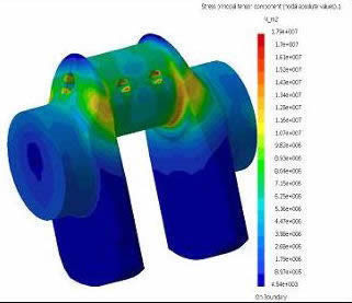
FEA simulation of crankshaft load
FEA uses a complex system of points called nodes which make a grid called a mesh. This mesh is programmed to contain the material and structural properties which define how the structure will react to certain loading conditions. Nodes are assigned at a certain density throughout the material depending on the anticipated stress levels of a particular area. Regions which will receive large amounts of stress usually have a higher node density than those which experience little or no stress. Points of interest may consist of: fracture point of previously tested material, fillets, corners, complex detail, and high stress areas.
The mesh acts like a spider web in that from each node, there extends a mesh element to each of the adjacent nodes. This web of vectors is what carries the material properties to the object, creating many elements.
So, structure is broken down into many small simple blocks or elements. The behavior of an individual element can be described with a relatively simple set of equations. Just as the set of elements would be joined together to build the whole structure, the equations describing the behaviors of the individual elements are joined into an extremely large set of equations that describe the behavior of the whole structure. The computer can solve this large set of simultaneous equations. From the solution, the computer extracts the behavior of the individual elements. From this, it can get the stress and deflection of all the parts of the structure. The stresses will be compared to allowed values of stress for the materials to be used, to see if the structure is strong enough.
The term "finite element" distinguishes the technique from the use of infinitesimal "differential elements" used in calculus, differential equations, and partial differential equations. The method is also distinguished from finite difference equations, for which although the steps into which space is divided are finite in size, there is little freedom in the shapes that the discreet steps can take. Finite element analysis is a way to deal with structures that are more complex than can be dealt with analytically using partial differential equations. FEA deals with complex boundaries much better than finite difference equations will, and gives answers to "real world" structural problems. It has been substantially extended in scope during the roughly 40 years of its use.
Finite Element Analysis makes it possible to evaluate a detailed and complex structure, in a computer, during the planning of the structure. The demonstration in the computer of the adequate strength of the structure and the possibility of improving the design during planning can justify the cost of this analysis work. FEA has also been known to increase the rating of structures that were significantly over designed and built many decades ago.
In the absence of Finite Element Analysis (or other numerical analysis), development of structures must be based on hand calculations only. For complex structures, the simplifying assumptions required to make any calculations possible can lead to a conservative and heavy design. A considerable factor of ignorance can remain as to whether the structure will be adequate for all design loads. Significant changes in designs involve risk. Designs will require prototypes to be built and field tested. The field tests may involve expensive strain gauging to evaluate strength and deformation.
With FEA, the weight of a design can be minimized, and there can be a reduction in the number of prototypes built. Field testing will be used to establish loading on structures, which can be used to do future design improvements via Finite Element Analysis.
Finite Element Analysis is done principally with commercially purchased software. These commercial software programs can cost roughly $1,000 to $50,000 or more. Software at the high end of the price scale features extensive capabilities -- plastic deformation, and specialized work such as metal forming or crash and impact analysis. Finite element packages may include pre-processors that can be used to create the geometry of the structure, or to import it from CAD files generated by other software. The FEA software includes modules to create the element mesh, to analyze the defined problem, and to review the results of the analysis. Output can be in printed form, and plotted results such as contour maps of stress, deflection plots, and graphs of output parameters.
The choice of a computer is based principally on the kind of structure to be analyzed, the detail required of the model and the type of analysis. An analysis can take minutes, hours, or days. Extremely complex models will be run on supercomputers. Usually, "Faster and Bigger is Better!" if you can afford it, and this might be called "The fundamental theorem of finite element analysis." People who analyze large structures, or run nonlinear models, will tell you that you can never get a machine that is as fast as you would like, and hopefully, good business sense will prevail. Many things can be analyzed in good detail on computers costing from roughly $2,000 to $20,000. Budget for a large monitor, fast graphics card, large hard drive, large memory, fast processor(s), and an appropriate printer. Color is usually desirable, although you can sometimes live without it by doing gray-scale plots. Higher prices will let you consider computers with more memory, larger hard drives, and one or more high-speed processors. Depending on the complexity of the structures to be studied and the volume of manufacturing, the expense for FEA hardware can be small in comparison with the savings in weight and construction cost that can result from design improvements, and speed of analysis. The expense can be very small in comparison to the cost of a failure. Problem is, when there is no failure, how do you "prove" that the investment was warranted? It helps if senior management trusts engineering staff and is at least somewhat familiar with the nature of their work. For example, BMW Sauber F1 Team can count on one of the most powerful supercomputers not only in Formula One, but in the automotive industry as a whole. "Albert", as the system has been christened, was built using a total of 530 processors in cluster architecture with dual nodes by Swiss firm DALCO. The processors are installed in high-density cooling enclosures supplied by American Power Conversion (APC). These enclosures are self-contained, closed-loop water circuits that provide up to 15 kW of cooling power per enclosure. The supercomputer comprises a total of ten enclosures, each one meter wide, a 1.20 meters deep and 2.30 meters high, resulting in a total width of ten meters and a weight of 18 tones. The technical data is as impressive as the "hard facts": the supercomputer boasts peak performance of 2.3 Tflop/s and is equipped with 1 TB RAM and 11 TB of hard-drive storage
To illustrate the point for non-computer experts, this means that "Albert" is capable of performing 2,332,000,000,000 computing operations per second. To achieve the same computing performance, the entire population of the city of Zurich (350,000) would have to multiply two eight-digit figures every four seconds for a whole year. The machine has over 1,085,440 megabytes of physical memory and over 10,880 gigabytes of hard-drive storage. Sauber uses all this power for calculations in CFD and FEA.
FEA analysisi of magnetostatic configuration of magnetic core
The background of a finite element analyst includes an understanding of engineering mechanics (strength of materials & solid mechanics) as well as the fundamentals of the theory underlying the finite element method. The analyst must understand the basics of numerical methods. An engineering degree is typical, though not an absolute requirement. Use of a particular finite element program requires familiarity with the interface of the program in order to create and load the models, and to review the results. To do the work well requires experience, comprehension of structures and their classical (manual analytical) analysis, an understanding of a variety of FEA modeling issues and an appreciation of the specialized field in which the design work is taking place.
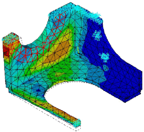
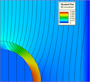
Structural analysis consists of linear and non-linear models. Linear models use simple parameters and assume that the material is not plastically deformed. Non-linear models consist of stressing the material past its elastic capabilities. The stresses in the material then vary with the amount of deformation as in picture.
Vibrational analysis is used to test a material against random vibrations, shock, and impact. Each of these incidences may act on the natural vibrational frequency of the material which, in turn, may cause resonance and subsequent failure.
Structures can be analyzed for small deflection and elastic material properties (linear analysis), small deflection and plastic material properties (material nonlinearity), large deflection and elastic material properties (geometric nonlinearity), and for simultaneous large deflection and plastic material properties.
Plastic material properties are when the structure is deformed beyond yield of the material, and the structure will not return to its initial shape when the applied loads are removed.
In addition to analyzing structures for their stress and deflection, other typical analyses are an evaluation of the natural frequency of vibration, and calculation of buckling loads. Steady state, transient, and random vibration behavior can be analyzed, too.
 |
 |
Building a Formula 1 or any other racing race car requires accurate analysis of structural features and constraints. Today, carbon fiber composites are a significant factor in F1 design. Although they account for only 20 percent of the car by weight, they comprise about 80 percent of its structure by volume. The monocoque chassis of a Formula 1 race car is a sandwich structure, made of high-performance carbon-epoxy composite face sheets and an aluminum or aramidic honeycomb core. High-modulus and high-strength composites, with aerospace-class toughened epoxy resins, are used in order to obtain the maximum safety performance/weight ratio. All attachment points for the engine, suspensions, roll hoop, etc., are made through inserts embedded in the lamination stack during the production phase. In order to minimize weight and thermal expansion differential, and maximize the adhesion, the inserts are made as thick (about 18-mm) laminated composite plates to be machined to the required dimensions and thickness.
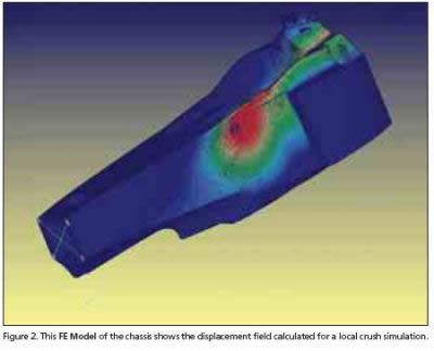
The safety regulation requirements are the main driver of the chassis design, both from the global lay-up and from the local reinforcement standpoints. There are a number of impact tests to pass. Basically, all of them are simulated in a finite element analysis (FEA) environment. Some of them can be replicated closely, while others cannot, for example penetration test. Where a realistic simulation of the test cannot be done, a simplified correlated calculation has been set up and validated with many years of experimental data base. Within those constraints, F1 design engineers constantly search for design or aerodynamic advantage that can shave fractions of a second from a lap time. Toward that end, each car of the team is redesigned before each season, followed by incremental design changes during the season.
Here, F1 design is unusual in one other respect as well. Unlike the product development cycles in aerospace, marine and even consumer automotive markets, which begin with a CAD design and then migrate to analysis, the F1 cycle starts with optimization of simulation and analysis data in a finite element analysis (FEA) environment (fed by the previous year's design), and then the simulation data drives the new design. FEA data are transferred to a CAD environment to create the car design, including carbon fiber ply schedules, core thicknesses and myriad of other variables.
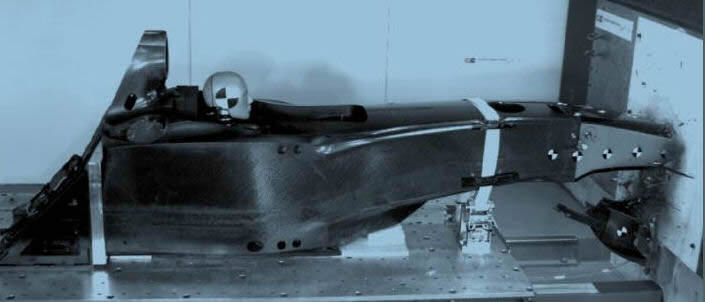
When McLaren and Lotus debuted cars in the 1983 Formula One season featuring CFRP (carbon fibre reinforced polymer) chassis, some of the biggest advances have been in the area of design and simulation. The behaviour of composites is considerably harder to predict than uniform materials: with finite element analysis method having been developed originally to model solid homogeneous and isotropic materials, simulations are naturally more complex for composites. It is the failure mode of composites that makes them hard to model. Traditional metallic structures absorb impact energy by deforming and folding. CFRP is very different, because the energy is absorbed by fracturing. The static simulation of CFRP is now well-developed, but accurate prediction of crash performance is somewhat harder, with FEA requiring significant real-world testing, reducing the benefits of FEA as a tool here.
The past decade has seen the rapid development of new modelling techniques that can predict the behaviour of composites, providing engineers with a much deeper understanding of what is and isn’t possible. The focus of these simulation and design packages is on the interaction between the separate plies of a composite structure, enabling components to be tailored to the load cases they receive, by optimising the composite lay-up, as in, for example, the number of plies or carbon cloth layers, direction of fibre weaves and local addition of material in high-stress areas. This provide engineers with the ability to build cars that are lighter and stiffer than was possible using other construction techniques, it also brought great benefits to driver safety.
The computer group at one Formula 1 team consists of 10 - 20 people who cover FEA, CFD (computational fluid dynamics), multibody, and hydraulics design and analysis. It takes approximately two months for operators to come to the first definition of the chassis structure. Then, including optimization, refining, and other changes, 25% of the team potential is dedicated to the chassis during a racing season. The workflow of the monocoque chassis structural design, from the conceptual phase issues to the regulation checks and the optimization process, requires accurate and easy-to-use analysis.
Currently, most of the teams use NeiNastran , ANSYS or FLUENT software as general-purpose FEA software for static analysis (stress, stiffness), buckling (linear-nonlinear, especially on crash cones), and surface contact (roll-bar crush). All of the calculations are correlated with experimental measurements, thus enabling a continuous refinement of methodologies and material data.
In order to reach the targets defined above, several optimization runs are made by modifying material choice, lay-up sequences, local reinforcements, foams, bulkheads, and inserts. In this phase, it is important that the FEA package be productive in managing and editing the existing FE model, solving the problem, and giving accurate and detailed post processing information, so effective modifications can be decided by the engineers.
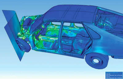
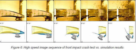
FEA visualization of SAAB crash test
Generally, FEA is the method of choice in all types of analysis in structural mechanics (i.e. solving for deformation and stresses in solid bodies or dynamics of structures) while computational fluid dynamics (CFD) tends to use FDM or other methods like finite volume method (FVM). This is especially true for 'external flow' problems, like air flow around the car or airplane, or weather simulation in a large area.
Few years ago, the biggest problem with work with all this different kind of software's (CAD, CAM, CFD and FEA software's) was importing and exporting results of one into another.
Sculptor software is now able to seamlessly link together CFD and structural analysis tools to solve fluid structure interaction.
Typically, the fluid flow produces pressures and/or temperatures which deform the surrounding structure. In turn, these structural deformations change the fluid flow field. The ability for software to recreate the interaction of a flexible structure immersed in a flowing fluid field is a critical component of the design stage for many fields of engineering. FSI is vital in determining the stability and response of an aircraft wing, the response of a high-pressure sensor introduced into a pipe flow, or a downforce generating wing on a racecar.
The importance of this design tool is often overshadowed by the difficulty to generate the numerical models for an FSI problem and the time required to establish a quality mesh. Modeling is further complicated by the dissimilar mesh requirements for the structural and fluid domains.
Formula 1 Race Car Design Takes Finite Element Analysis To the Next Level (PDF) (Dennis Sieminski, Nora Engineering)