Camshaft and Variable Valve Timing
Go to Formula 1 engine valve actuation
The camshaft is a part of piston engines and is used to operate poppet valves. It consists of a cylindrical rod running the length of the cylinder bank with a number of oblong lobes or cams protruding from it, usually one for each valve. The cams force the valves open by pressing on the valve, or on some intermediate mechanism, as they rotate.
Depending on the location of the camshaft, the cams operate the valves either directly or through a linkage of pushrods and rockers. Direct operation involves a simpler mechanism and leads to fewer failures, but requires the camshaft to be positioned at the top of the cylinders. In the past when engines were not as reliable as today this was seen as too much bother, but in modern gasoline engines the overhead cam system, where the camshaft is on top of the cylinder head, is the most common. Some engines use two camshafts each for the intake and exhaust valves; such an arrangement is known as a double or dual overhead cam (DOHC), thus, a V engine may have four camshafts. The most common camshaft arrangements are:
- Single overhead camshaft(SOHC),
 |
|
|
 |
 |
Pushrod valve actuation system - became very rear in modern auto industry) |
The relationship between the rotation of the camshaft and the rotation of the crankshaft is critical. If cylinder heads and pistons are the heart of an engine, then the camshaft and valve train are the brain of the operation. Timing the opening, closing, lift, and duration of each valve event is central to get any power and torque. Since the valves control the flow of air/fuel mixture intake and exhaust gases, they must be opened and closed at the appropriate time during the stroke of the piston. For this reason, the camshaft is connected to the crankshaft either directly, via a gear mechanism, or indirectly via a belt or chain called a timing belt or timing chain. In some designs the camshaft also drives the distributor and on early fuel injection systems, cams on the camshaft would operate the fuel injectors.
v
BMW F1 engine timing gear
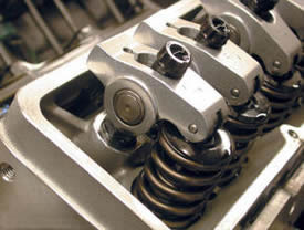
Now I'm going to get technical: The valves that admit air-fuel mixture into the engine's combustion chambers, and that open to allow the burned gasses to be pushed out as exhaust, are controlled by egg-shaped lobes on these camshafts, as you see on the first image on the top of the page.
The shape of those lobes, and their positioning on the shaft, determine a cam's timing. In most cases, cam timing is fixed, and that means that it's a compromise that provides optimal performance only at the speed at which the engine is likely to do most of its work.
But engines operate over a wide range of speeds, from an idle speed of about
600-900 rpm to a peak speed of more than 6,000 rpm. The problem with fixed valve timing that the valve train is set by the auto maker for peak efficiency running at a specific point in the engine's operating range. When the engine is rotating slower or faster than this ideal operating point, the engine's combustion cycle fails to properly burn the air/fuel mixture leading to considerably compromised engine performance and wastes fuel. It turns out that there is a direct relationship between the shape of the cam lobes and the way the engine performs in different speed ranges.
To understand why this is the case, imagine running an engine extremely slowly at just 10 or 20 revolutions per minute (RPM) so that it takes the piston a couple of seconds to complete a cycle. To actually run an engine this slow would be impossible, but let's imagine that we could. At this slow speed, we would want cam lobes shaped so that just as the piston starts moving downward in the intake stroke, the intake valve would open. The intake valve would then close right as the piston reaches the bottom and the exhaust valve would then open right at the end of the combustion stroke and would close as the piston completes the exhaust stroke.
This kind of setup would work really well for the engine as long as it ran at this very slow speed.
Now what happens if you increase the RPM?
When you increase the RPM, the 10 to 20 RPM configuration for the camshaft will not work very well.
Just say if the engine is running at 4,000 RPM, the valves are opening and closing 2,000 times every minute, or 33 times every second. At these speeds, the piston is moving incredibly fast, so the air and fuel mixture rushing into the cylinder will also be moving at a very quick rate.
When the piston starts its intake stroke and the intake valve opens, the air/fuel mixture in the intake runner starts to accelerate into the cylinder. By the time the piston reaches the bottom of its intake stroke, the air/fuel mixture is moving at a pretty high speed. If you slam the intake valve shut, all of that air/fuel mixture would come to a halt and will not enter the cylinder. By leaving the intake valve open a little longer, the momentum of the fast-moving air/fuel mixture continues to force and compress air and fuel into the cylinder even when the compression stroke is already started by the piston. In theory the faster the engine goes, the faster the air/fuel mixture flows and the longer we would want the intake valve to stay open. We would also want the valve to open wider at higher speeds to improve volume of the mixture.
Also affecting the cams performance is lift, the duration, overlap and timing. To know a bit more, check airbox article.
Lift refers to maximum valve lift. This is how much the valve is "lifted" off its seat at the cam lobe's highest point. The intake and exhaust valves need to be open to let air/fuel in and exhaust out of the cylinders. Generally, opening the valves quicker and further will increase engine output. Increasing valve lift, without increasing duration, can yield more power without much change to the nature of the power curve. However, an increase in valve lift almost always is accompanied by an increase in duration. This is because ramps are limited in their shape which is directly related to the type of lifters being used, such as flat or roller.
Duration is the angle in crankshaft degrees that the valve stays off its seat during the lifting cycle of the cam lobe. Increasing duration keeps the valve open longer, and, if it's done properly, can increase high-rpm power. Doing so increases the RPM range that the engine produces power. By increasing duration without a change in lobe separation angle will result in increased valve overlap.
Overlap is the angle in crankshaft degrees that both the intake and exhaust valves are open. This occurs at the end of the exhaust stroke and the beginning of the intake stroke. Increasing lift duration and/or decreasing lobe separation increases overlap. At high engine speeds, overlap allows the rush of exhaust gasses out the exhaust valve to help pull the fresh air/fuel mixture into the cylinder through the intake valve. Increased engine speed enhances the effect. Therefore increasing overlap, increases top-end power and reduces low-speed power and idle quality.
To conclude, any given camshaft will be perfect only at one engine speed. At every other engine speed, the engine won't perform to its full potential. A fixed camshaft is, therefore, always a compromise.
What if cam timing could be optimized over the engine's entire operating range?
There are a couple of ways by which car manufacturer's vary the valve timing. The most well known system is the VTEC which is used on some of the Honda engines.
Variable valve timing has changed all negative points of fixed camshafts. By coming up with a way to alter valve timing between high and low rpm's, Honda, Toyota, BMW and all other manufacturer's can now tune valve operation for optimum performance and efficiency throughout the entire rev range. The timing of the camshaft can now be advanced to produce better low end torque or it can be retarded to produce better high end torque.
 Honda was the first to offer what it called VTEC in its Acura-badged performance models like the Integra GS-R and NSX (it has since worked its way into the Prelude and even the lowly Civic). VTEC stands for Variable Valve Timing and Lift Electronic Control.
Honda i-VTEC
The basic functionality of VTEC is surprisingly simple, well-used and very reliable. Again, it is a kind of compromise because it is optimized for only two rev ranges. VTEC allows the valves to remain open for two different durations. A short opening time for low-speed operation to give good torque and acceleration, and a larger opening time for higher speeds to give more power. To do this, the camshaft has two sets of cam lobes for each valve and a sliding locking pin on the cam follower that determines which lobe is operating the valve. The locking pin is moved by a hydraulic control valve based on the engine speed and power delivery requirements. The two lobe shapes are referred to as fuel economy cams and high power cams, meaning that Honda engines with this technology are really two engines in one - a performance engine and an economical engine. As a VTEC driver, you can both hear and feel the change when the VTEC "kicks in" at higher rpm levels to improve performance. While this system does not offer continuously variable valve timing, it can make the most of high rpm operation while still providing solid drivability at lower rpm levels.
The problem with Honda's idea is that you really only have two modes - economy and power. In this way Honda offer improvements to old system, but was still only offering two compromises instead of old one. Honda improved this system with new i-VTEC (intelligent VTEC), to provide continuous timing variation of the intake camshaft on DOHC i-VTEC engines. On the VTEC-E engines, with SOHC 3 valve, an oil pressure actuated solenoid is activated when certain conditions are met and the second of the two intake valves opens and closes with the first.
Toyota saw the success Honda was having with VTEC (from both a functional and marketing standpoint) but decided to go a different route. Instead of the on/off system that VTEC employs, Toyota decided it wanted a continuously variable system that would maximize valve timing throughout the rpm range, so rather than simply having economy and power modes, there's an infinite number of positions in between that can be selected on-the-fly in fractions of a second. This means that the engine can be kept in its "sweet spot" for a far broader range of operating conditions and demands. Dubbed VVT-i for Variable Valve Timing with intelligence (Is this a dig at Honda, suggesting their system isn't intelligent?), Toyota uses a hydraulic rather than mechanical system to alter the intake cam's phasing. The main difference from VTEC is that VVT-i maintains the same cam profile and alters only when the valves open and close in relation to engine speed. This means that whilst the actual duration that the valves are open never changes, their timing in relation to all the other engine operations can be adjusted. In a simple engine, the timing belt, gear train or chain from the crankshaft loops up and around a camshaft pulley that turns the camshaft. With VVT-i, the timing belt loops around a pulley that contains hydraulic fluid or oil. The camshaft itself has vanes on the end of it that sit inside the fluid, so in this system, the camshaft is not directly linked to the timing belt pulley. By altering the oil pressure through a series of valves, the position of the camshaft vanes can be altered inside the pulley housing. Also, this system works only on the intake valve while VTEC has two settings for the intake and the exhaust valves, which makes for a more dramatic gain in peak power than VVT-i can claim. VVTL-i, Variable Valve Timing with Lift and Intelligence is the latest Toyota improvement in this area presented in Celica, and this system continuously varies the timing of the intake valves. System varies duration, timing and lift of the intake and exhaust valves by switching between two different sets of cam lobes.
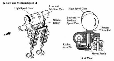 This is the Toyota VVTL-i in the low/medium rev setting. The small cam lobe runs on a small follower which itself is a part of a 'U' shaped device that operates both valves. The big cam runs on its own follower, but that follower has nothing to work against .... At the moment.
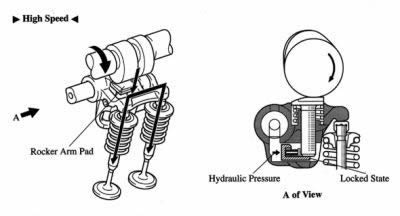
The device has now swapped over to high rev operation, and if you look at the left hand diagram you can see how hydraulic pressure has moved a small pin under the big cam's follower, thus making the connection and so making the valves follow the big cam's profile.
 Ferrari has a really neat way of doing this. The camshafts on some Ferrari engines are cut with a three-dimensional profile that varies along the length of the cam lobe. At one end of the cam lobe is the least aggressive cam profile, and at the other end is the most aggressive. The shape of the cam smoothly blends these two profiles together. A mechanism can slide the whole camshaft laterally so that the valve engages different parts of the cam. The shaft still spins just like a regular camshaft, but by gradually sliding the camshaft laterally as the engine speed and load increase, the valve timing can be optimized.
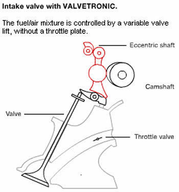
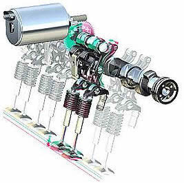
BMW has also used a cam phasing system, called VANOS (Variable Onckenwellen Steuerung) and Valvetronic for several years. Like the other manufacturers, this system only affected the intake cams. But, as of 1999, BMW is offering its Double VANOS system on the new 3 Series and Valvetronic systems. As you might have guessed, Double VANOS manipulates both the intake and exhaust camshafts to provide efficient operation at all rpm's
This helps the new 328i, equipped with a 2.8-liter in-line six, develop 193 peak horsepower and 206 pound-feet of torque. More impressive than the peak numbers, however, is the broad range of usable power that goes along with this system.
It seems only fair to mention two German solutions given there are two Japanese solutions mentioned before. Audi's system is very similar to Honda's in that is uses a relatively simple mechanism to choose between two differently-shaped cam lobes. In principle, it works just like i-VTEC, the only real difference is the mechanism used to select the cam lobes. Instead of having two cam followers and a locking pin, Audi use a pair of sliding cam lobes on a splined part of the camshaft. The sliding lobe carrier is moved along the camshaft to determine which of the two lobes will be used to operate the valves. Frankly, I think this is much cleverer than the BMW system, but I'm sure some sort of engineering war would erupt if they heard me say that out loud.
Are there more types of VVT-s? Sure there are. Several other manufacturers, including Ford, Lamborghini and Porsche have jumped on the cam phasing bandwagon because it is a relatively cheap method of increasing horsepower, torque and efficiency.
Basically every manufacturer and their respective top models have some form of variable valve timing now. Hopefully the five designs on top of this page will give you some idea of the different engineering solutions to the same problem.
I'm not going to cover all the other types - they're all variations of the four already covered here. So next time the motoring bore in the pub asks you if you know how VVT works, you can geek out on him. Won't get you many women, but at least you'll sound like you know what you're talking about.
Here is list of manufacturers and their respective VVT technologies:
- Alfa Romeo - CVVT, Double continuous variable valve timing, used on inlet and exhaust valves on Twin Spark engine
- BMW - VALVETRONIC, VANOS and Double VANOS.
VANOS - Varies intake timing by rotating the camshaft in relation to the gear.
Double VANOS - Continuously varies the timing of the intake and exhaust valves.
VALVETRONIC - Provides continuously variable lift for the intake valves; used in conjunction with Double VANOS. - Fiat "StarJet" FIRE-based engine.
- BMW/PSAPeugeot Citroën - CVVT , Continuous variable valve timing
- Chrysler - Dual VVT, dual Variable Valve Timing. Used on Chrysler GEMA "World" engine. Varies valve timing through the use of concentric camshafts developed by Mechadyne enabling dual-independent inlet/exhaust valve adjustment on the 2008 Dodge Viper.
- Daihatsu - DVVT, Dynamic variable valve timing
- Ford - VVT, Variable valve timing. Varies valve timing by rotating the camshaft.
- General Motors - VVT, Variable valve timing, Varies valve timing continuously throughout the RPM range for both intake and exhaust. DCVCP (Double Continuous Variable Cam Phasing) - Varies intake and exhaust camshaft timing continuously with hydraulic vane type phaser.
- Kia - CVVT, Continuous variable valve timing
- Honda - VTEC Varies duration, timing and lift by switching between two different sets of cam lobes. i-VTEC In high-output DOHC 4 cylinder engines the i-VTEC system adds continuous intake cam phasing (timing) to traditional VTEC. i-VTEC does not necessarily have two sets of cam lobes like traditional VTEC. In economy oriented SOHC and DOHC 4 cylinder engines the i-VTEC system increases engine efficiency by delaying the closure of the intake valves under certain conditions and by using an electronically controlled throttle valve to reduce pumping loss.
- Hyundai - CVVT, Continuous variable valve timing - provides continuous variable valve timing on Intake, Fuel System and Exhaust all independently controlled
- Mazda - S-VT - The ECU calculates intake timing and actuates an oil control valve to modulate oil pressure on intake camshaft.
- Mitsubishi - MIVEC Varies valve timing, duration and lift by switching between two different sets of cam lobes. The 4B1 engine series uses a different variant of MIVEC which varies timing (phase) of both intake and exhaust camshafts continuously.
- MG Rover - VVC, Variable Valve Control
- Nissan - CVTCS, Continuous Variable Valve Timing Control System. The ECU adjusts the engine's timing continuously. N-VCT - Varies the rotation of the cam(s) only, does not alter lift or duration of the valves. VVL - Varies timing, duration, and lift of the intake and exhaust valves by using two different sets of cam lobes.
- Porsche - VarioCam varies intake timing by adjusting tension of a cam chain. VarioCam Plus varies intake valve timing by rotating the cam in relation to the cam sprocket as well as duration, timing and lift of the intake and exhaust valves by switching between two different sets of cam lobes.
- Toyota - VVT - Toyota introduced VVT in the 1992 Corolla GT,
VVT-i Variable Valve Timing with intelligence Continuously varies the timing of the intake camshaft, or both the intake and exhaust camshafts (depending on application), and VVTL-i, Variable Valve Timing with Lift and Intelligence continuously varies the timing of the intake valves. Varies duration, timing and lift of the intake and exhaust valves by switching between two different sets of cam lobes. - Volvo - CVVT, Continuous variable valve timing
- Wolkswagen Group - Similar to VarioCam, the intake timing intentionally runs advanced and a retard point is calculated by the ECU. A hydraulic tensioner retards the intake timing. Most modern VW Group petrol engines now include VVT on either the inlet cam or both inlet and exhaust cams.
In addition to mechanical friction, considerable force is required to overcome the valve springs used to close the engine's valves. This can amount to an estimated 25% of an engine's total output at idle, reducing overall efficiency. Several engine manufacturers are experimenting with systems that would allow infinite variability in valve timing and reduce this mechanical friction. For example, imagine that each valve had a solenoid on it that could open and close the valve using computer control rather than relying on a camshaft. With this type of system, you would get maximum engine performance at every RPM. Some approaches to reclaiming this "wasted" energy include:
· Springless valves, like the desmodromic system employed today by Ducati
· Camless valvetrains using solenoids or magnetic systems have long been investigated by BMW and Fiat.
· The Wankel engine, a rotary engine which are not using neither pistons or valves, best known for being used by Mazda in the RX-7 and RX-8 sports cars.
Camless valvetrains using solenoids or magnetic systems have currently being prototyped by Valeo and Ricardo. Something to look forward to in the future!
 |
Electro - magnetic valve system |
 |
Electro - hydraulic valve system |
 |
Hydraulic valve system |
Go to Formula 1 engine valve actuation