In Formula 1 aerodynamicist spending countless hours and milions of dollars perfecting a front wing endplate to get a gain worth 0.008s. Hardly worth the bother, you might think, but add that to infinitesimal but continual developments elsewhere on the car and you start getting somewhere. This kind of work they call "marginal gains", a concept that chases tiny improvements by focussing on details that, on their own, seem irrelevant but, collectively, can make a massive difference.
The text of this article is courtesy of:
Willem Toet, Head of Aerodynamics,
Sauber F1 Team, Sauber Motorsport AG
Parts of the article added by me is separetly stated as (Added by SEAS) and writen with this font.
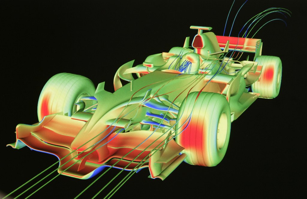
Aerodynamics of F1
Why is so much money and energy spent looking at the shapes of Formula 1 (F1) cars? Fundamentally because it pays dividends. If you can reduce the drag of the car you will go faster on the straights. If you can use the shape of the car to generate some downward pressure (usually called downforce) onto the tires, then the car will go faster around the corners. Research into aerodynamics has allowed cornering speeds in “high speed” corners to be much higher than that which is possible without the use of aerodynamic aids, although it has reduced ultimate top speeds. Track lap times have improved significantly.
We all know that, speaking generally, the forces exerted by aerodynamics increase with the square of speed. |
The aerodynamics of F1 cars is intensively researched and annual 5% - 10% downforce increases have been possible if rules don’t change too much between seasons. Due to the nature of the vehicles, the aerodynamics of F1 cars are quite different to that of road cars – with drag coefficients of between 0.7 and 1.0 (it used to be even higher but rules restrict how much area can be used for aerodynamic devices) – this is between about 2 and 4 times as much as a good modern road car. This is partly due to the rules (running exposed wheels is part of the definition of an open-wheeled racing car) and partly because downforce is usually much more important than drag.
Aerodynamic research in F1 has been an area of high investment in the past 30 years. Assuming no regulatory limitations, this trend would continue while the bodywork rules are changed continually or while changes to the shape of the cars continue to provide significant improvements in lap time around the F1 circuits of the world. However, agreements between teams started to limit investment and now rules have been introduced officially to limit how much research is done into aerodynamics in wind tunnels and in CFD. Naturally teams will optimize their resources to still obtain the maximum they can from the aerodynamics of the cars.
 To investigate the aerodynamics of a F1 car the teams use various methods of research. Tests are conducted using scale models of the cars in a wind tunnel fitted with a “rolling road”. Computers are used to mathematically simulate the flow of air around and through the cars and to model vehicle behavior on the track. The real cars used to be tested as well in wind tunnels and on special straight line test facilities, but this is now banned. Cars are tested on the real tracks of course, but that too is limited to fewer test days than was possible in the past. Each of the top 10 F1 teams has somewhere between 50 and 150 people working solely on aerodynamic research. It is quite difficult to be sure about how many people work on aerodynamics as generally the teams don’t talk about it. Despite the limits on track testing and on aerodynamic research that have been imposed by the rule makers (the FIA) and by agreements between the team, the amount of research done is “significant”. Even a “small” team of 50 people can do a lot of work!
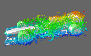 |
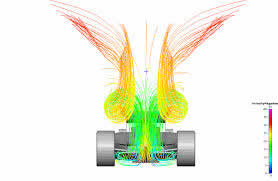
Computation of a Formula 1 meeting with the 2010 regulations (Added by SEAS) |
Teams use computer simulation more and more to predict performance and to analyze many “what if” scenarios. These simulations are then constantly improved by comparing them to the realities of racing and testing. From these tools we know that the drag of the cars does slow them down quite a lot but typically, on an average race track, it slows them by about 3% - 5% in lap time. In other words, if drag were to be reduced to zero, the gain in lap time at a typical track would normally be a bit less than 5%. However, if we remove the present levels of downforce then lap times get slower by about 25% or so.
In the present F1 environment, other performance factors which are normally very important have been limited more severely. E.g. the tires are all supplied by one supplier and are carefully randomly selected for the teams by the rule makers and tire supplier together so there is no chance of one team getting an advantage. The tire supplier selects 2 of the 4 dry options they make for the season plus one intermediate and one extreme wet tire. So you cannot develop your own tire to get an advantage. In the 5 years to 2014 engine specifications were, effectively, frozen. For 2014 there is a completely new powertrain formula but the idea is that these powertrains will also be virtually frozen once a reasonable level of parity is established. Cars must race above a certain minimum weight (to protect against dangerous construction as low weight helps lap time). Suspension kinematics is relatively free so this is an area where the teams can make a difference, but suspension must be passive. However, because aerodynamics is so dominant, even this is compromised to ensure aerodynamics benefits are maximized.
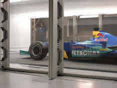
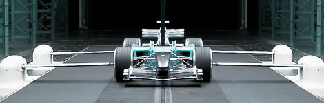
 The wind tunnel models used for testing are either 50% or 60% (60% upper limit in F1) of full scale and are tested up to 60 hours per week. In the past the tunnels were used 24 hours per day 7 days per week and some teams had more than one wind tunnel working, but rules now limit that (check the FIA rules about Wind tunnel and CFD testing limitation on the end of this article). The floor of the wind tunnel is replaced with a “rolling road” (a fancy name for conveyor belt) and a boundary layer removal system (that removes the slow-moving air that builds up on a stationary surface) to simulate the fact that the car rolls over the ground. These rolling roads
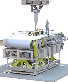 |
Moving ground plane or rolling road systems employ steel belt technology, air bearings and sophisticated hexapod model motion systems to optimize the accuracy of F1 aerodynamic testing. (Added by SEAS) |
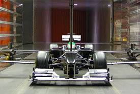
and boundary layer control systems are essential for racing car work and are a science in themselves. Most teams test their models at 50 m/s (=180 kph) which is the highest speed the teams are permitted to use by the regulations (more was possible in a few facilities which is why the limit was imposed, The Sauber wind tunnel is one of the best in F1, capable of testing full-scale cars on a rolling road at speeds up to 300 kph.). To approach a realistic representation of the aerodynamics on a real (full-scale) car, it is best to test a large model as fast as possible, allowing for all the difficulties involved. All simulation methods, whether computer or wind tunnel testing, have their strengths and their limitations. One way that teams can make a difference to performance is through the understanding of these factors and the methods employed to take advantage of the strengths and to cover the weaknesses of each type of simulation. The other way is though the quality and/or volume of testing the teams do. Real-car track testing is a vital part of this process but is too slow, imprecise and expensive a method to be the only sort of testing a team should do. The variations in temperature, wind, track condition, tires, driver input variations, etc. is why track testing is not as precise as testing in a controlled environment. It is though the most important reality we try to simulate. Track testing is also limited by regulation so the teams experiment with new parts mainly on Friday practice sessions at a grand prix weekend.
 |
 |
After they reach a certain speed, race
cars begin to behave less and less like
automobiles and more like airplanes. With race speeds climbing ever higher,
you need increasingly advanced tools to
help you understand the aerodynamic
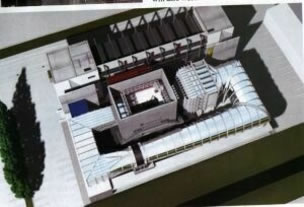
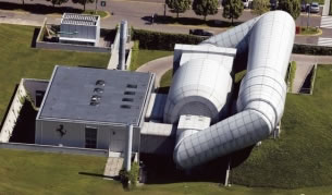
properties of your vehicle designs. Sauber (left) and Ferrari (right) wind tunnel are two of this tools. Ferrari had a power of 2.2 MW at the design stage. Sauber has 3.0 MW. That is effectively 36% more power. The Sauber tunnel is much longer and wider. Ferrari's was designed for 50% scale and Sauber's for 60% but can also run full size car. Sauber can turn the rolling road 10% off the axis and simulate cornering. They also have more length in the chamber to simulate two cars behind each other. Ferrari cannot do that. The Ferrari tunnel is exposed to the environment (outer walls will heat and cool down with outside temperature) and the Sauber tunnel is entirely covered by a building which will have an influence on internal temperature control. Perhaps, problems with Ferrari wind tunnel are due to external parts. These parts are affected by external temperature changes. |
|
Sauber Wind Tunnel: |
Ferrari Wind Tunnel: |
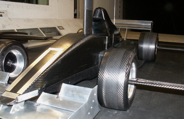 The highest proportion of aerodynamic research money and energy is spent by most teams on the wind tunnel testing of scale models of the car. The models are not usually constructed in the same way or using the same materials as a real car. They are designed to simulate both the internal and external shape of the cars while enabling the teams to change the design of the model shape more simply than would be possible on a miniature replica of the real car. An average example might be a 50% scale model of the car using a wind speed of 50 m/s (=180kph). The model is usually suspended from the roof of the tunnel and is packed full of motors, load cells, pressure-measuring equipment, computers and other electronics. Sometimes wheels are not attached directly to the model but are held in place via mounts from outside the model. This has been found to give better overall repeatability of force measurement.
However, wheels-on-model is more accurate and is more commonly used. The teams routinely conduct tests over a range of ride heights and pitches (differences in front and rear height to the ground) while assessing model (as well as wheel) forces and scanning pressures. The effect of exhaust gas, roll, yaw and steer are conducted regularly as well. Graphical or tabulated results are displayed on monitors during the tests and the final result is seen shortly after the last measurements are taken. Every team is different so this is only a guide. High-speed dynamic movement of the models has been tried by some ambitious teams but the mechanical forces involved are so high that this has not proven to be a reliable development method. However, there has been a strong trend toward continuous motion of the model in the tunnel (a sort of slow-motion grand prix simulation).
Mathematical modelling and computational fluid dynamics (CFD) are the areas of the most rapid growth in effort in racing car aerodynamics at the moment. Computers are used to back up real-car and rig testing of things like water and oil cooling, assessing what level of drag and downforce will give the best lap time at a particular track in any given conditions, etc. In-house circuit simulation and lap-time prediction programs are used to assess the effect of aerodynamic gains (as well as engine power, gear ratios, gear-change time, weight, centre of gravity height, cooling, mechanical set-up, etc.) on lap time. Driver simulators take this world of simulation yet another step closer to the reality of a car on track.
 CFD is coming into its own as far as racing car aerodynamics are concerned. Modern super computers allow the use of mathematical models that mean complete and reasonably realistic full-vehicle aerodynamic simulations are now possible, if a little slow. The teams have now mainly settled on a CFD method called Navier Stokes which copes well with the realities of racing cars. Some teams are combining the use of commercially available packages with in-house computer programs/enhancements to maximise the gains that can be made using the computers. It will be some time before it is possible to dispense with wind tunnel testing because wind tunnels allow us to very quickly test hundreds of combinations of conditions and vehicle attitudes.
Both wind tunnel testing and CFD are now limited by the FIA in its Sporting Regulations. In the wind tunnel teams are limited by wind-on time (about 15 hours per week) plus a maximum of 80 runs per week and 60 hours per week tunnel occupancy. CFD simulations are limited to a certain number of teraflops of solver time. Together wind-on time and teraflops are limited to 30 units in total so, if use 15 hours of “wind on” time per week, we can use 15 teraflops of computer power to solve CFD cases.
 |
Sauber had the fastest supercomputer in industrial use in Europe named Albert 2 located at its HQ in Hinwil, Switzerland, introduced in December 2006. Albert 2 was using 1,024 Intel processor cores (256 compute nodes, each with two Intel Xeon 5160 dual core processors), have a total memory of 2,048GB and a maximum power of 12,28 TFlops (12.288 GFlops - approximately 12,288,000,000,000 calculations per second), based on Intel Technology (processors, mainboards and chassis) and with a total weight of 21 Tons. An extension of 32 more compute nodes to a total of 288 nodes or 1.152 processor cores was added soon afterwards. During 2009., BMW Sauber F1 Team has launched the next step by extending the existing system. A further 384 nodes, equipped with Intel Xeon E5472 quad core processors (four cores per processor) and related Intel technology where added to the existing system so that the new supercomputer, Albert3,with 4224 cores. The main memory grew to 8448 GBytes and the peak compute power was 57,7 TFlops, (50.700.000.000.000 arithmetic operations per second). The new supercomputer, like its predecessor, was developed by DALCO. Necessary software was provided by German subsidiary of US-based Ansys-Fluent. New Albert 3 has a total weight of 38 tons and covers an area of only 24 square meters. Sauber no longer use Albert 2 or 3 and have much less powerful computers as CFD is limited in the regulations.(Added by SEAS) |
All the methods of improving car aerodynamics have their limitations. Testing everything you want to try on a real car is very expensive (engines, tires, travel to the test tracks, personnel, etc) and has limited precision – plus this sort of activity is strictly limited. Atmospheric, track, tire and driving changes, for example, mean that small (aerodynamic) steps cannot be reliably assessed. Wind tunnel model testing works reasonably well in a straight line but realistic tire shape changes at the contact patch are difficult to match to reality and important to aerodynamics. Of course more aerodynamic downforce is only really needed when the driver is not able to drive at full throttle, such as when accelerating at low speed, cornering or braking. To simulate cornering in a wind tunnel is simply not practical as a racing car on the limit of adhesion is sliding all the time and the angle that the air approaches the front and the rear of the car is not the same. It is possible to steer the wheels of the model and to yaw the model.
Of course any limitation irritates engineers, so improvements are constantly sought and we get ever closer to being able to simulate real cornering. The more realistic the simulation of the tire deformation, the more likely that the model tires will wear out and this can restrict what a team can achieve because model tires (also supplied by Pirelli) are restricted to 12 sets per year. While real-cornering simulation is not quite there yet for wind tunnel testing, these sorts of cases are at least theoretically possible using CFD. However, assessing sensitivity of forces to ride height, pitch, roll, yaw, steer and sliding through a corner are significantly slower than in a wind tunnel.
Generally, the approach taken today is to evolve from a baseline using wind tunnel testing and CFD, with most (but not all) CFD results checked in the wind tunnel, and then to make an update for the real car. This update is then tested on the real car to ensure that there are actually benefits. By conducting thousands of tests in the wind tunnel and using CFD for every real-car update, the aerodynamic step is usually large enough that the improvement is obvious to the drivers and quickly seen as an improvement in lap time. Should an update fail to impress, it is back to the drawing board for the Aerodynamicists to try and understand why. It is for reasons of updates to the car not performing particularly well and research into why this happened that some teams test in the wind tunnel in a yawed and steered condition (for example). Furthermore, it will continue to be the main driving force behind future improvements in the simulation techniques that the teams use.
Much of what the teams do is limited by the (bodywork) rules that govern the sport. It is because of the rules that there are flat-stepped floors on race cars with no car-to-ground bridging devices, the teams run exposed rather that covered wheels, have an open cockpit of certain minimum dimensions and virtually none of the wings or aerodynamic devices is movable or even flexible. Driver-controlled rear wing movement (upper element only, DRS) is allowed with extremely strict limitations and limited driver-initiated deployment under control of the rule makers. No material (even solid steel) is infinitely rigid and most teams have experimented with the limits of flexibility of the so-called rigid aerodynamic devices. As a result, the rule makers regularly adapt and refine specific flexibility limitations where they add a load to certain parts of the car and measure the deflection, which must be less than a rule-dictated limit. Suspension (mainly) parts cannot be wing-shaped and have to be of neutral section, i.e. the same top and bottom shapes, and have to be fitted “horizontally” with a tolerance of ± 5 degrees (more than enough to be able to play with). Rules also govern overhangs, heights, widths, etc. Despite the limitations of the rules, teams are able to work in many areas and continually increase the downforce without increasing the drag. Much of the work done now involves the understanding of airflow in 3 dimensions and it is mainly as understanding improves that aerodynamic efficiency of the cars is increased. It really isn’t possible to work on one part of the car in isolation (at least not for long) as everything interacts.
Many of the technical regulations change from time to time for reasons of safety. For example, there are tests for front impact, rear impact, side impact, top crush, floor (fuel cell) puncture – none of which may damage the chassis of the car. The cockpit must be a certain minimum dimension and shape, with energy-absorbing foam around the driver’s head, shoulders and legs, and a driver’s seat that can be removed from the car with the driver still seated in it. These safety regulations obviously influence what the teams can do aerodynamically speaking with the shape of the car.
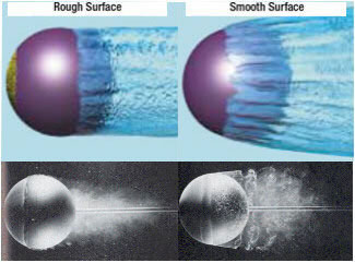 Most of the ideas received by various teams from untrained enthusiasts are either illegal or more relevant to supersonic flow (which works more in line with untrained ideas of flow geometry) than to the subsonic flow on racing cars. It is, for example, not intuitive to people without aerodynamic training that there is more likely to be separation around a wing (a stall) at low speed (70 kph, say) than at high speed (250 kph). The other most common idea presented to reduce drag is the use of a dimpled or rough surface, via a “golf-ball” or shark skin effect. This and many other surface-finish treatments have been tried by most teams and found to be of no or, at best, little benefit. This is partly because skin friction only changes the drag of a Formula 1 car a very small amount (it is a much bigger deal for aircraft, for example). Research into surface treatments and micro-vortex generators continues.
 Racing car wings are installed “upside down” compared to aircraft wings. This means that, on a racing car, the more curved or convex surface faces downward and rearward, whilst the flatter or sometimes concave surface faces upwards or forwards. On racing cars, it is the underside of the wing which is relatively more important than the top surface. Wings work because of air speed differences (caused by the shape of the wing) which in turn cause pressure differences – the faster the local flow caused by the shape of the wing, the lower the pressure and vice-versa. Wings working in “ground effect”, that is wings reasonably close to the ground, are in general more effective (produce more downforce) than those a long way from the ground. Increasing the angle of the wing slows down the air on top of the wing and thus increases its static
  (surface) pressure, while speeding up the air under the wing leading edge decreases the static pressure there. The mid part of the front wing is a fixed neutral section dictated by regulation. There is no limit to the angle of attack (picture left) of the rest of the front wings as such other than aerodynamic stall but the rules limit wing position (the wing has to fit into a number of boxes or zones). The optimum front wing design is mainly dictated by the influence the front wing then has on the flow to the underbody of the car and the rear wings. Despite the regulations, the front wing still contributes a high proportion of the downforce of the car. For performance reasons all the front wing shapes are 3-dimensional in that the shape is different inboard to outboard.
The aerodynamic set-up of a modern F1 racing car is unlikely to be the same at any 2 races in a year. Aerodynamic settings (such as the front and rear wings) and hence the drag of the car are optimized to suit individual circuits. In addition, different brake ducts (for circuits where brakes are used more or less than an “average” circuit) and engine cooling exit ducts are fitted. Then, as a result of aerodynamic research, regular aerodynamic updates are made that change some feature of the car. These might be wings or body parts with a totally new shape. There are of course other settings and updates (e.g. suspension settings & suspension parts, electronics, engine, etc.), that are not directly aerodynamic, that ensure that the car is certainly never raced twice in the same configuration.
The downforce produced by the cars aerodynamically makes a big difference to grip. In a high-downforce configuration the cars produce their own weight (including driver) in aerodynamic download by around 36 m/s (=129 kph or 80 mph). This means that if, at that speed, you were upside down on the roof of a theoretical “tunnel” you would stay there. In truth, in order to maintain control over the vehicle you would need enough grip to steer the car and to apply enough power to overcome the very high drag of the car. So you would really have to go at about 45 m/s (=162 kph or 100 mph) to drive one of our cars upside down in a straight line.
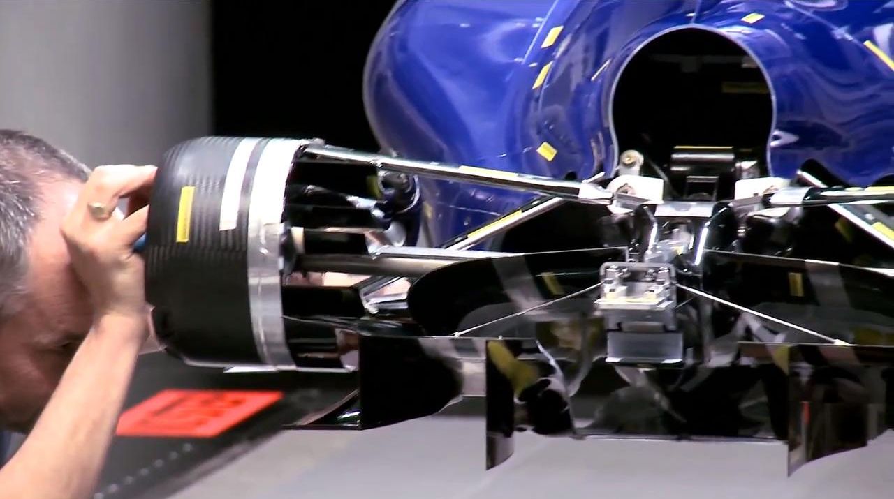
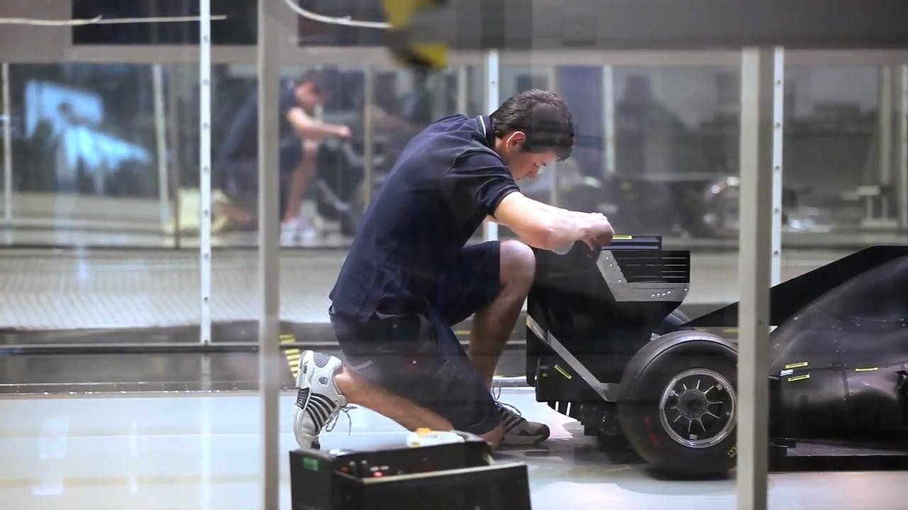
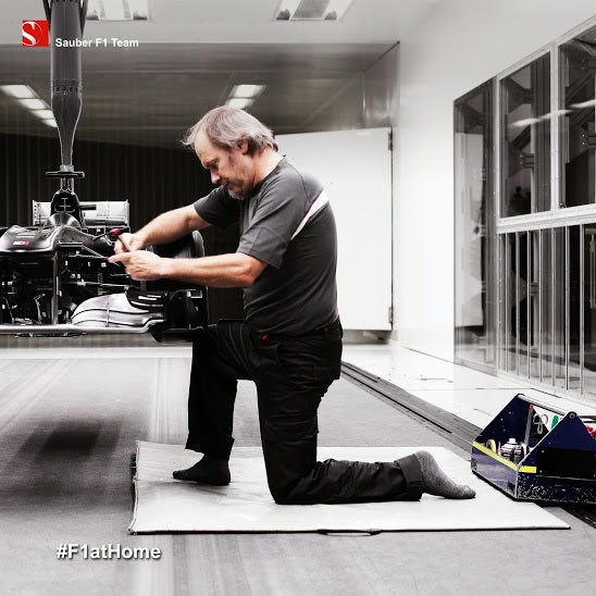 |
Wind tunnel at the Sauber F1 Team factory. Detail, work on the 60% model. (Sauber on Instagram) |
Willem Toet, Head of Aerodynamics,
Sauber F1 Team, Sauber Motorsport AG
Blockage |
Usually referred to as a percentage, this is the ratio of the frontal area of the vehicle being tested to the cross-sectional area of the wind tunnel. For a solid tunnel 4-5% would be a typical “good” value. Higher numbers would begin to require significant blockage correction. |
Blockage Correction |
Forces directly measured on a wind tunnel model are often “corrected” to allow for the effects on forces caused by the (close proximity of the) walls of the wind tunnel. Typically this will involve reductions in both the drag and lift values with different corrections for each. The “correction” factors are typically derived from standard bluff bodies tested at many blockages. |
As air passes over a stationary surface, the air nearer the surface moves more slowly than air further away. Over time and distance, this layer of slow-moving air builds up. This is the boundary layer. |
|
Contact Patch |
The point where the tire touches the road. Being flexible, the tire is squashed locally creating a contact patch, which increases as the vertical load on the tire increases. Simplified you could imagine that the tire is cut by the plane of the road. |
Double Diffuser |
A diffuser is limited in size by regulation and creates downforce by creating a pressure differential, with low pressure beneath and higher pressure above. Clever interpretation of the rules regarding holes in the floor and continuous surfaces led to the openings that allowed double diffusers. Effectively the step formed two separate, but individually continuous, surfaces allowing airflow to pass up above the step plane into the upper deck of the diffuser. This rule was clarified for 2011 and now a single continuous surface must be formed under the floor. |
(See DRS below). Active systems (eg Mercedes system where air was channelled through an opening in the rear-wing endplate when the DRS was activated and then fed through the car to help stall the front wing) banned for 2013 and beyond. Passive systems (sometimes known as Drag Reduction Devices [DRDs]) with no moving parts other than the airflow through them are still allowed. |
|
For the purist, this should be referred to as “negative lift”, since most aerodynamic devices were invented for aircraft and were designed to lift them into the air. It is the vertical part of the aerodynamic force generated by the car as it moves through the air. |
|
This is the horizontal part of the aerodynamic force generated by the car as it moves through the air. This force is so great on a F1 racing car that, when the driver comes off the throttle at maximum speed, the car slows down at least as briskly as a road car can brake at maximum effort. |
|
Drag Coefficient |
Usually shown as Cd or Cx. Changes as a function of the shape of the body. Drag force changes as a function of Cd or Cx and flow direction, fluid/air density and viscosity, object position and size, and speed; and is proportional to the density of the fluid/air and to the square of the relative speed between the fluid/air and the object. |
An overtaking aid which allows the driver to make an adjustment to the rear wing from the steering wheel and deactivated when the driver brakes. Can only be used in DRS zones (designated areas of the track) in qualifying and, during the race, if the following car is within one second of the car in front at the DRS detection points. Race Director may decide to suspend use in adverse weather conditions or in a yellow-flag zone. The rear wing flap must be at least 10mm from the main plane when closed and no more than 65mm when open. |
|
The exhaust from a F1 engine exits the tailpipe at high speed (was approximately 1100 kph/700 mph in 2013) depending on exhaust pipe diameter and temperature. This exhaust gas can, in certain circumstances, be used to reduce drag or increase downforce. In other circumstances, it can do quite a bit of damage, due to its extremely high temperature, severely damage the car mechanically (such as melting the wings). For 2014 exhaust diameters have been increased (which then reduces speed in the pipes) and moved to an area where less (aero-wise) can be achieved. |
|
McLaren were the first to use. They managed to redirect airflow over the rear wing, allowing the flap to stall and increasing top speed by a few kph, and controlled by a vent in the cockpit which could be blocked by the driver’s leg. The rules were then clarified and, from 2011, any system, device or procedure which uses driver movement as a means of altering the aerodynamic characteristics of the car is prohibited. |
|
A curved aerodynamic surface influences the airflow even a long way from that surface, bending the airflow in such a way that flow adjacent to the surface follows that surface almost perfectly. The further away from the surface you go, the straighter the flow becomes. When an aerodynamic surface is placed close to the ground, the presence of the ground determines where the flow becomes straight. This has the effect of speeding up the airflow between the surface and the ground, increasing the aerodynamic effect of the surface. |
|
When the front and rear ride heights are different to one another; the car is said to be pitched. Pitch can be expressed as an angle or as a difference between the front and rear ride heights. |
|
Reynolds Number |
Ratio of speed, length and air density to fluid/air viscosity. At low levels of Reynolds Number (ie equal to or below 2300) flow is laminar, at higher levels (ie above 4000) is turbulent and, in between, is in transition. |
Height or average height of the car to the ground. Each team has its own plane or point of reference for ride height. |
|
This is the difference in ride height left to right and is usually expressed as an angle to the ground. |
|
When an aerodynamic surface curves too quickly for the air particles to follow the shape of the surface, the airflow is said to be stalled. |
|
Steer |
Turning the steering wheels (front in F1) at an angle to the vehicle. Just like the effect of turning the steering wheel in a road car. |
Subsonic |
Literally, below the speed of sound. The reason this is important in aerodynamics is that there is a dramatic, almost switch-like, change in the way air behaves when the speed of sound is reached. |
Supersonic |
Above the speed of sound. At supersonic speeds, airflow sometimes appears as a shock wave and seems to move in straight lines. |
Swirling flow of air. A vortex would occur at the tip of a wing where the air passing around the wing is deflected just beside air that does not touch the wing. The sudden change in flow angularity created by the meeting of these two different flow directions creates the swirling mass of air. Rear-wing vortices can be seen on racing cars in damp conditions. Sometimes vortices are generated on purpose to control airflow such as the small angled rectangles that protrude above many aircraft wings. F1 teams are investigating vortex generators to push the limits of aerodynamic downforce further than they now can. |
|
A car is said to be in yaw when it corners with a sliding (usually tail-out) attitude. In other words, the car is cornering sideways. |
The text of this article is courtesy of:
Willem Toet, Head of Aerodynamics,
Sauber F1 Team, Sauber Motorsport AG
22) TRACK RUNNING TIME OUTSIDE AN EVENT AND WIND TUNNEL TESTING
22.1 Testing of Current Cars (TCC) shall be defined as any track running time, not part of an Event, in which a competitor entered in the Championship participates (or in which a third party participates on behalf of a competitor), using cars which were designed and built in order to comply with the 2013, 2014 or 2015 Formula One Technical Regulations. No competitor may sell or make available a car of the current year to any third party without the full knowledge of the FIA.
Each competitor will also be permitted to carry out two Promotional Events (PE) with the above cars which will not be considered TCC. A PE shall be defined as an event in which a competitor participates purely for marketing or promotional purposes. No such test may exceed 100km in length and only tyres manufactured specifically for this purpose by the appointed supplier may be used.
In order that an FIA observer may be appointed, competitors must inform the FIA of any planned TCC or PE at least 72 hours before it is due to commence, the following information should be provided :
i) The precise specification of the car(s) to be used.
ii) The name(s) of the driver(s) if known.
iii) The nature of the test.
iv) The date(s) and intended duration of the test.
v) The purpose of the test.
22.2 Testing of Previous Cars (TPC) shall be defined as any track running time, not part of an Event, in which a competitor entered in the Championship participates (or in which a third party participates on behalf of a competitor), using cars which were designed and built in order to comply with the 2010, 2011 or 2012 Formula One Technical Regulations.
TPC may only be carried out with cars built to the specification of the period and only tyres manufactured specifically for this purpose may be used.
In order that an FIA observer may be appointed, where possible competitors must inform the FIA of any planned TPC at least 72 hours before it is due to commence, the following information should be provided :
i) The precise specification of the car(s) to be used.
ii) The name(s) of the driver(s) if known.
iii) The nature of the test.
iv) The date(s) and intended duration of the test.
v) The purpose of the test.
22.3 Testing of Historic Cars (THC) shall be defined as any track running time, not part of an Event, in which a competitor entered in the Championship participates (or in which a third party participates on behalf of a competitor), using cars which were designed and built in order to comply with the 2009 Formula One Technical Regulations or earlier.
THC may only be carried out with cars built to the specification of the period and only tyres manufactured specifically for this purpose, or tyres of the period, may be used.
22.4 Competitors may only participate in TCC, TPC or PE using cars which have been subjected to, and fulfilled the requirements of, the tests described in Articles 16.2-6, 17.2-3 and 18.2-9 of the F1 Technical Regulations.
Any car used for TCC or PE must be fitted with the panels described in Articles 15.4.7 and 15.4.8 of the F1 Technical Regulations.
Any car used for TPC must be fitted with the panels described in Article 15.4.7 of the F1 Technical Regulations.
22.5 No competitor may carry out more than 15,000km of TCC during a calendar year.
22.6 No TCC may take place :
a) Whilst a Championship Event is taking place.
b) With more than one car per day at any such test.
c) Before 09.00 or after 18.00 on any day at any such test.
d) On any track located outside Europe without the agreement of the majority of teams and the FIA.
e) During the month of August except under (h) below.
f) Prior to 20 January. [Note : Revert to previous date for 2015]
g) Between 20 January and the start of a ten day period which precedes the start of the first Event of the Championship of the same year with the exception of three team tests of no more than four consecutive days duration, carried out on a site approved by the FIA for Formula 1 cars. [Note : Revert to previous date for 2015]
One day, from any of these tests but no less than 20 days before the start of the first Event of the Championship, must be set aside for testing of wet-weather tyres. Arrangements for this day of testing will be made by the appointed tyre supplier in full consultation with the teams and the FIA.
h) Between the start of a ten day period which precedes the start of the first Event of the Championship and 31 December of the same year with the following exceptions :
i) Four team tests of no more than two consecutive days duration carried out on circuits where an Event has just taken place, such tests commencing no less than 36 hours after the end of the relevant Events.
The number of tests will be reduced if the number of Events during a Championship season exceeds 20, one test will be cancelled for each Event above 20.
In the interests of providing the appointed tyre supplier with access to current F1 cars for the purposes of tyre development, all teams will be obliged to allocate one date from amongst the eight in-season test days for testing tyres :
- Allocation of dates will be negotiated with the appointed tyre supplier who will give priority to teams according to their positions in the previous year's Championship.
- Allocations must be declared by each team to the FIA before the start of the first Event of the Championship and may not be subsequently changed.
- The team must test tyres on the allocated day according to run plan defined by the appointed tyre supplier.
- The run plans and results for each day of tyre testing must be made available to all teams.
- Tyres used during such testing day will not be drawn from the team's annual allocation of tyres for testing.
ii) If a team declares that one of its current race drivers is to be substituted by a driver who has not participated in an F1 race in the two previous calendar years, one day of TCC will be permitted between the start of a ten day period which precedes the start of the second Event and the last Event of the Championship. The following must be observed :
- Any such day may only be carried out by the new driver and may not take place on a circuit hosting a race in the current Championship year.
- Any such day may only take place within a period 14 days prior to the substitution and 14 days after the substitution has taken place.
- If a team, having declared the driver's substitution and performed the test, does not then enter an Event with the new driver, the team will be penalised by a reduction of one day from the pre-season TCC days available in the following year.
22.7 During all TCC and TPC cars must be fitted with the FIA ECU required by Article 8.2 of the FIA Formula One Technical Regulations.
22.8 No TCC is permitted at sites which are not currently approved for use by Formula 1 cars.
22.9 During all Formula One TCC :
a) Red flag and chequered flag procedures must be respected.
b) No other type of vehicle is permitted on the track.
c) Cars being driven by drivers who do not possess a Super Licence must be fitted with a green rear light which must be illuminated at all times the car is on the track.
d) Every reasonable effort should be made to ensure that the recommendations concerning emergency services detailed in Article 16 of Appendix H to the Code are followed.
22.10 If, after an incident during TCC and TPC, the Medical Warning Light signals that threshold forces have been exceeded the driver must present himself for examination in the circuit medical centre without delay.
22.11 Competitors must abide by the aerodynamic testing restrictions set out in Appendix 8.
22.12 All competitors must observe a shutdown period of fourteen consecutive days in the month of August during the time that two consecutive Events are separated by at least twenty four days. Competitors should notify the FIA of their intended shutdown period within 30 days of the start of the championship season.
During the shutdown period no team, nor any of its suppliers, may carry out any of the following activities for or on behalf of the team :
a) Operation or use of any wind tunnel (excluding any service and maintenance activity).
b) Operation or use of any computer resource for Restricted CFD Simulations (excluding any service and maintenance activity).
c) Production or development of wind tunnel parts, car parts (including the powertrain), test parts or tooling.
d) Sub-assembly of car parts (including the powertrain) or assembly of cars.
e) Any work activity by any employee, consultant or sub-contractor engaged in development or production (excluding any work activity to be undertaken at the race track in preparation for the Event immediately following the shutdown period).
Each competitor must notify its suppliers of the dates of its shutdown period and must not enter into any agreement or arrangement with the intention of circumventing the prohibition on the above activities.
22.13 During the shutdown period the following activities will not be considered a breach of the above :
a) Repairs carried out with the agreement of the FIA to a car seriously damaged during the Event preceding the shutdown period.
b) The assembly and servicing of running or static show cars, none of which may entail the production, assembly or servicing of any current car parts.
c) The operation and use of any wind tunnel or computer resource for Restricted CFD Simulations provided this is being carried out for projects with no direct relation to Formula One or for or on behalf of a competitor that is not at that time within its own shutdown period.
d) Any activity the sole purpose of which is supporting projects unconnected to Formula One, subject to the written approval from the FIA.
APPENDIX 8
AERODYNAMIC TESTING RESTRICTIONS
The Aerodynamic Testing Restrictions, and the definitions and rules which will apply to aerodynamic testing, are as follows :
1. Restricted Wind Tunnel Testing
1.1 In the context of this Appendix the word bodywork will have the same definition as that provided by Article 1.4 of the F1 Technical Regulations.
1.2 Restricted Wind Tunnel Testing is the testing by a Team or any Related Party of that Team, or any agent or sub-contractor of the Team or any of its Related Parties, in a test environment of a representation of an F1 car or subcomponent in order to measure, observe or infer any forces, displacements, pressures or air flow direction resulting directly or indirectly from the incident air flow. The only allowable exceptions from this definition are as follows :
a) Wind tunnel testing which aims to develop components associated with cooling, or the running of the engine from a boundary commencing at the engine air intake duct, passing through the engine and finishing at the exit of the exhaust tailpipes, provided that there is no direct or indirect measurement of aerodynamic force during the test. In this context, pressure and flow measurements within a duct shall not be considered to be measurements of aerodynamic force.
For the avoidance of doubt, any wind tunnel testing to develop bodywork parts other than as referred to in sub-paragraph (a) above even without aerodynamic force measurement is within the definition of Restricted Wind Tunnel Testing.
In some cases a testing rig which was devised to develop components associated with cooling or the running of the engine could have the potential to offer secondary benefits for bodywork development. Specific examples of such rigs and the additional restrictions that apply to them are provided in section 5.
b) Any aerodynamic test conducted by an F1 car at any Event.
c) Any aerodynamic test conducted by an F1 car during and at Track Testing as permitted by the F1 Sporting Regulations.
1.3 No Restricted Wind Tunnel Testing may be carried out using a scale model which is greater than 60% of full size.
1.4 No Restricted Wind Tunnel Testing may be carried out at an air speed exceeding 50m/s.
1.5 Restricted Wind Tunnel Testing may only be used in wind tunnels which have been nominated by the Team to the FIA.
1.6 The Restricted Wind Tunnel Testing fluid must be air at atmospheric pressure.
1.7 During Restricted Wind Tunnel Testing only one model may be used per test and only one model change is permitted per wind tunnel per 24 hour period. Compliance with this restriction will be determined upon the time elapsed between the wind speed exceeding 15m/sec with successive models, not upon the occupancy of the wind tunnel test section by successive models. For the avoidance of doubt, a model in this context is defined by its underlying spine, motors and sensors. Detail changes to the aerodynamic configuration of a given model remaining in the wind tunnel are permitted.
1.8 During Restricted Wind Tunnel Testing, once the air speed rises above 15m/s the bodywork of the test car or subcomponent must remain fixed until the air speed returns below 1m/s with the exception of any freedom set out in section 6.
2. Restricted CFD Simulations
2.1 Restricted CFD Simulations are computational fluid dynamic (CFD) simulations by a Team or any Related Party of that Team, or any agent or sub-contractor of the Team or any of its Related Parties, of flows that are gaseous in the case of the full size F1 car and are not classified as Engine Simulations. Any simulation of flows contained within the engine cooling or lubrication systems, air, air/fuel mixtures, combustion process or products of combustion from a boundary commencing at the engine's atmospheric air intake ducts, passing through the engine and finishing at the exit of the exhaust tailpipe will be classified as an Engine Simulation.
2.2 For the avoidance of doubt, if any CFD simulation (other than the Engine Simulation defined above) reveals information about flows that are gaseous on the full size F1 car then it is a
Restricted CFD Simulation. For example; any CFD simulations conducted at scales other than 1:1 or using non gaseous fluids are still Restricted CFD Simulations as they reveal information about flows that are gaseous on the full size F1 car.
2.3 Restricted CFD Simulations refer to the solver part of the process (irrespective of the numerical scheme behind the simulation) plus any mesh adaptation included in a solver optimisation loop. Pre-processing, mesh creation and post processing of CFD simulations are unrestricted. Only the calculation part of the process (iteration time) shall be included in the Restricted CFD Simulations.
2.4 Restricted CFD Simulations do not apply to calculations made for the purpose of optimising CFD methodology, provided they use a physical car geometry which is more than 12 months old, and this car geometry is not added to, removed from, morphed or modified.
2.5 Restricted CFD Simulations may only be carried out using hardware that has been nominated by the Team to the FIA.
The declaration of the hardware by the Team to the FIA will include :
a) The name and model number of the Processing Unit.
b) Number of Processing Unit cores in the cluster.
c) Peak number of double precision floating point calculations per cycle per core of the Processing Unit.
d) Further to clause 2.5(c), in the case of an Intel CPU with either the Sandybridge or Ivybridge chipset where the team chooses not to exploit the AVX feature; the team must explicitly declare and be able to demonstrate that they are NOT using the AVX feature in the CFD solve process. If the non-usage of the AVX feature is proven to the auditor, the Intel Sandybridge and Ivybridge chipset cores can be rated as 4 flop/cycle/core rather than as 8 flop/cycle/core.
e) Further to clause 2.5(c), in the case of a Processing Unit without a double precision floating point operating capability the number of natural precision operations per cycle per core will be used instead. As an example, a single precision only GPU core will count the number of single precision floating point operations per cycle.
f) Processor speed at which the Processing Unit is configured to run at 100% CPU load.
g) Any off load engines used within the cluster.
h) Maximum Teraflops (flop=double precision floating point operation) the system can use. This may exclude any AVX floating point operations if declared under 2.5(d) or include natural precision operations under 2.5(e).
2.6 The calculation used for the declaration of the 8 week Aerodynamic Testing Period shall be carried out as below.
TotFLOPS = (MFPPC * CCF * NCU * NSS ) / (604,800 * 8 * 1000)
Where :
TotFLOPS = The total number of TeraFLOPs used per CFD solve run.
MFPPC = Peak double precision floating point operations per cycle per core of the Processing Unit (excluding AVX if declared under 2.5(d) or using natural precision operations under 2.5(e) if the core is not double precision capable).
CCF = Peak Processing Unit clock frequency in GigaHertz achieved during the CFD solver run. This will be the peak frequency theoretically achievable during the run based on one of the following :
a) The standard clock frequency value from the Processing Unit Manufacturer's specification sheet (if overclocking or enhanced modes are not used in the run).
b) The maximum “turbo”, “HPC” or other enhanced mode frequency value.
c) The maximum overclocked frequency value.
NCU = Number of Processing Unit cores used for the run.
NSS = Number of solver wall clock seconds elapsed during the run. NB Message passing time during calculation should be included.
All information required for auditing should be present in the output from the run including the CCF value.
For the avoidance of doubt, any offload processing for example FPU, FPGA, GPU/GPGPU, VFP, softfp etc. should be included and calculated using the same method as above.
3. Combined Restricted Wind Tunnel Testing and Restricted CFD Simulation Restriction
3.1 The usage limits for Restricted Wind Tunnel Testing and Restricted CFD Simulations are expressed in terms of Wind On Time, number of runs, tunnel occupancy and CFD Teraflops Usage during an Aerodynamic Testing Period.
3.2 An Aerodynamic Testing Period is an eight week period used for evaluation of these restrictions. As soon as one Aerodynamic Testing Period finishes, a new one begins. The start and finishing dates for each Aerodynamic Testing Period for a given calendar year will be published by the FIA at the start of each calendar year.
3.3 Wind On Time is defined as the amount of time (in hours) per week, averaged over the
Aerodynamic Testing Period, where the wind tunnel air speed exceeds 15m/s for Restricted Wind Tunnel Testing. For the avoidance of doubt any Restricted Wind Tunnel Testing performed for the Team by any Related Party of that Team, or any agent or sub-contractor of the Team or any of its Related Parties during an Aerodynamic Testing Period must be included in this calculation as if the tests were performed by the Team.
3.4 CFD Teraflops Usage is defined as the average number of teraflops of computing power used for the purpose of making Restricted CFD Simulations during the Aerodynamic Testing Period.
For the avoidance of doubt, computer resource used for Restricted CFD Simulations that fail or are aborted by the user must still be included in the CFD Teraflops Usage calculation. For the further avoidance of doubt any Restricted CFD Simulations performed for the Team by any Related Party of that Team, or any agent or sub-contractor of the Team or any of its Related Parties during an Aerodynamic Testing Period must be included in this calculation as if the simulations were performed by the Team.
3.5 Each Team must limit Restricted Wind Tunnel Testing and Restricted CFD Simulations so that at the end of each Aerodynamic Testing Period it can be demonstrated that the Team has operated according to the Limit Line.
3.6 The Limit Line is defined as follows :
WT <= WT_limit (1 – CFD/CFD_limit)
Where :
WT = Wind On Time
WT_limit = 30 hours
CFD = CFD Teraflops Usage
CFD_limit = 30 Teraflops
3.7 The limit in CFD simulation (“CFD_limit” in the Limit Line) will be revised every three years, starting from 1st January 2014, to a new performance level to take account of changes to CFD hardware ownership and running costs.
3.8 Each Team must also limit Restricted Wind Tunnel Testing to a maximum of 80 runs per week and a maximum of 60 hours of tunnel occupancy per week. At the end of each Aerodynamic
Testing Period it will also have to be demonstrated that the Team has operated according to these Limits.
4. Reporting and Benchmarking
4.1 Each Team must declare to the FIA in writing the computer resource that is employed for the purpose of Restricted CFD Simulations. If the hardware is changed or upgraded then a new declaration must be submitted to the FIA within one month of the change.
4.2 Each Team must declare to the FIA in writing the wind tunnel resource that is employed for the purpose of Restricted Wind Tunnel Testing. If a different facility is to be used or if the existing facility is significantly changed or upgraded then a new declaration must be submitted to the FIA within one month of the change.
4.3 Each Team shall report to the FIA details of its Restricted Wind Tunnel Testing and Restricted CFD Simulations for the preceding Aerodynamic Testing Period within 7 days of the end of that Aerodynamic Testing Period. The data must be provided in the format specified by the FIA.
This declaration shall be based on records of the solution time of each Restricted CFD Simulation to a precision of at least the nearest second and on records of the Wind On Time of each wind tunnel run performed during Restricted Wind Tunnel Testing to a precision of at least the nearest second.
4.4 In order to check on the hardware employed by the Teams and as a means of assuring common application of the restrictions set out in this Appendix, the FIA will arrange for independent benchmarking inspections of both Wind Tunnel and CFD activities to be carried out from time to time. Recommendations arising from these inspections will be incorporated into this Appendix.
5. Exceptions to definition of Restricted Wind Tunnel Testing
5.1 Free testing is permitted (and therefore not within the definition of Restricted Wind Tunnel
Testing) for development of suspension and steering systems (Article 10 of the F1 Technical
Regulations), brake systems (Article 11 of the F1 Technical Regulations) and wheels and tyres
(Article 12 of the F1 Technical Regulations) provided such tests do not concurrently test (or in any way provide incidental data or knowledge) concerning performance or endurance of parts or systems classified as bodywork.
5.2 Steady State and Dynamic engine dynamometer work with an F1 car or subcomponent may be performed (and therefore not within the definition of Restricted Wind Tunnel Testing) provided that :
a) The bodywork used in the test has no front wing assembly (Articles 3.7.2 to 3.7.8 of the
F1 Technical Regulations) or rear wing assembly (the whole of Article 3.10 of the F1
Technical Regulations) present.
b) No devices designed to measure directly or indirectly aerodynamic forces or flow field characteristics are installed in the facility used.
c) No sensor installed on the car or subcomponent which are capable of measuring displacements, pressures or air flow direction of the external airstream resulting directly or indirectly from the incident air flow may be logged. Logging files have to be available, if required, during the independent benchmarking inspection.
d) The gas flow exiting from the exhaust system is ducted away from the testing area before impacting on any bodywork component (other than the exhaust itself).
6. Bodywork Items that may be adjusted during a Restricted Wind Tunnel Testing Run
6.1 The following degrees of freedom are permitted during the course of a Restricted Wind
Tunnel Testing run :
a) The flap angle of a front wing may be adjusted.
b) The incidence of the rear most and uppermost element of the top rear wing may be adjusted.
Back to the top of the page